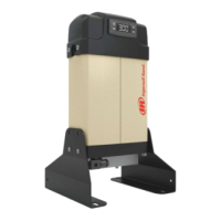
This document describes the Ingersoll Rand DA Heatless Purge desiccant dryer, designed to remove water vapor from compressed air.
Function Description
The DA series dryer operates by diverting compressed air flow alternately between two towers filled with desiccant material. While one tower adsorbs water vapor from the compressed air stream (drying cycle), the opposite tower is regenerated by desorbing accumulated water vapor and venting it to the atmosphere (regeneration cycle). Inlet flow is directed to the bottom manifold, and outlet flow exits through the upper manifold. Both pneumatically actuated valves and check valves in the manifolds direct air flow.
During the drying cycle, saturated compressed air enters the designated drying tower via normally-open inlet flow valves. Only one inlet valve closes to direct flow. Wet compressed air flows through the desiccant material, where water vapor is removed by adsorption.
The regeneration cycle involves two stages. First, tower depressurization occurs when inlet flow valves switch, diverting air away from the regenerating tower, and the normally-closed purge valve opens, depressurizing the tower. Rapid depressurization strips a significant portion of adsorbed water vapor, exhausting it to the atmosphere. The second stage uses a portion of dry, compressed air, expanded to atmospheric pressure, to complete desorption. This air flows through a purge orifice, expands, and continues the regeneration process, releasing water vapor into the regeneration air, which is then exhausted through the purge muffler.
DA Heatless Dryers are equipped with a downstream purge feature, utilizing air from a downstream source to purge the regenerating tower. This minimizes air compressor cycling, especially with downstream dry storage tanks. Purge air flow is factory preset to ensure proper dryer performance; setting it too high wastes compressed air, while setting it too low prevents achieving the desired dew point.
The dryer is controlled by a digital controller with an illuminated display and keypad on the main panel. The controller manages all dryer timing functions.
Usage Features
- Operating Conditions: Designed for compressed air inlet temperatures from 68°F (20°C) to 120°F (49°C) and operating pressures from 60psig (4barg) to 200psig (14barg). The standard dryer operates at 100°F (30°C) @ 100psig (7barg). The factory should be consulted for operation below 60psig (4barg) or above 100°F (38°C) to verify sizing and configuration.
- Dew Point Performance:
- -40°F (-40°C) units: Inlet valve position switches every five minutes. Tower regeneration occurs for 4 minutes and 10 seconds, followed by purge valve closing for repressurization.
- -100°F (-70°C) units: Inlet valve position switches every two minutes. Tower regeneration occurs for 1 minute and 50 seconds, followed by purge valve closing for repressurization.
- -100°F (-70°C) dryers require continuous air flow to achieve design dew point levels. Deadheading (no air flow) will result in elevated outlet dew points.
- Energy Management System (EMS) (Optional): Minimizes purge air use during low flow or low water loading conditions. A dew point sensor monitors moisture content from the online tower, providing a signal to the controller. The dew point transmitter should not be installed until the dryer has operated continuously for 24 hours.
- Compressor Interlock Function (DA40IM - DA300IM only): Reduces purge cycle timing based on compressed air demand by monitoring the air compressor's load/unload relay. Field wiring to the compressor's normally-open contact is required. This function is independent of EMS; if EMS is active, the interlock must be set to "OFF." It can serve as a backup for purge air reduction if the dew point monitor is removed.
- Installation:
- Lift the dryer only at identified lift points using proper equipment (crane, hoist, slings, or fork truck) to avoid injury and damage.
- Bolt the dryer to the foundation via bolt holes in the base frame (minimum 1 inch (25 mm) anchor bolt protrusion).
- DA5IM-DA25IM models can be wall-mounted.
- Prefilters (shipped loose) should be located as close to the dryer as possible with drains to prevent liquid water from entering desiccant beds.
- The wet air inlet is at the lower manifold, and the dry air outlet is at the upper manifold.
- An optional three-valve bypass system is recommended for 24/7 operations or during troubleshooting/servicing to avoid interrupting compressed air flow.
- All piping joints must be soap bubble tested at line pressure to check for leaks. Installed piping must be self-supported.
- Electrical Connection: All electrical connections must follow the wiring diagram (SECTION 9). The dryer must be grounded with a full-size ground wire. Overcurrent protection (circuit breakers or fuses rated for 115VAC, 15A) is required per NFPA70.
- Start-up Procedure:
- Complete and submit the Startup Form with the Warranty Card.
- Visually inspect the dryer for damage (piping, pressure vessels, gauges, control air hoses, filter bowls, differential pressure indicator fasteners).
- Ensure prefilter drains are blowing freely to drain residual water; if no moisture, turn the drain stem to the automatic position.
- Turn the field disconnect switch to ON to apply power. Verify voltage matches the serial plate. Do not apply power or activate operation until all checks are complete.
- Press the ON button on the dryer controller to initiate operation.
- Slowly open the outlet air shut-off valve (if equipped) and allow the system to slowly pressurize.
- Verify the compressed air system remains pressurized.
- Shut-down Sequence:
- The dryer must remain pressurized.
- Press the red "OFF" button to deactivate the operating sequence and de-energize control valves.
- The main flow valves will default: purge valve closes, regenerating tower repressurizes, main inlet flow valves open.
- The status line on the home screen will display "OFF."
- The system remains pressurized; no provisions for system bleed down.
- The "OFF" button only de-activates the operating sequence; electric power remains live in the main panel.
Important Technical Specifications
- Models: DA5IM, DA15IM, DA25IM, DA40IM, DA55IM, DA70IM, DA100IM, DA150IM, DA200IM, DA250IM, DA300IM.
- Electrical: 115/1/60 for all models.
- Air In/Out Connections (dryer):
- DA5IM-DA25IM: 3/8" BSPP
- DA40IM-DA70IM: 3/4" BSPP
- DA100IM-DA300IM: 1" BSPP (for -40°F), 1.5" BSPP (for -100°F)
- Air In/Out Connections (filter):
- DA5IM-DA25IM: 3/8" NPT
- DA40IM-DA70IM: 1/2" NPT (DA40IM), 3/4" NPT (DA55IM-DA70IM)
- DA100IM-DA300IM: 1" NPT (for -40°F), 1.5" NPT (for -100°F)
- Dew Point Monitor (EMS Option): The dew point transmitter assembly is supplied as a separate component and should not be installed until the dryer has been in operation for 24 hours.
- Controller Display Screens: Provide visual status of dryer operation, cycle information, configuration, and alarms. Includes initialization, anti-short-cycle countdown, home screen (operating status, cycle step, seconds remaining, drying/regeneration flow arrows), and optional dew point transmitter readings. Alarm status and service reminders are also displayed.
- Dryer Alarms (DA40IM-DA300IM only): Predefined elapsed time alarms that can be reset. Include filter element change (6 months), mufflers (12 months), dew point sensor (12 months), valves (36 months), and desiccant change (48 months).
- Dryer Communication RS485 (DA40IM-DA300IM): RS485 port with D+ Tx/Rx+ (B), D- Tx/Rx- (A), T+ Positive Termination, T- Negative Termination, and SG Signal Ground signals.
- Angle Valve Rebuild Parts: Includes valve, angle, 3/4" P.O.N.C. (Part No. 17933374) and 1/2" P.O.N.C. (Part No. 47681287001), with corresponding replacement actuator part numbers, seal rebuild kit part numbers, and mounting tools. Mounting tools are required for normally-closed valves to decompress springs and for safe dismantling.
Maintenance Features
- Daily Maintenance:
- Check and record inlet pressure, temperature, and flow.
- Check tower pressure gauge readings (DA40IM-DA300IM only).
- Check dryer operation for proper cycling, depressurization, and re-pressurization.
- Verify prefilter drain operation and absence of condensate from purge mufflers.
- Verify purging tower pressure is ≤ 3psig (0.2barg); if higher, muffler replacement is recommended.
- Check dryer digital controller for alarms (DA40IM-DA300IM only).
- Verify prefilter and afterfilter differential pressure is within operating limits; replace elements/cartridges as needed.
- Monthly Maintenance:
- Check muffler condition by reading tower pressure gauge during regeneration; if pressure > 3psig (0.2barg), muffler replacement may be required.
- Ingersoll Rand recommends cleaning mufflers after initial start-up to remove desiccant dust. This procedure should be repeated within the first seven days of dryer operation.
- Semi-Annual Maintenance:
- Check outlet dew point (EMS option only).
- Replace prefilter and afterfilter elements and/or cartridges.
- Annual Maintenance:
- Check desiccant and replace if necessary.
- Inspect and clean pilot air control solenoid valves, check valves, and flow valves; rebuild and/or replace as required.
- Replace drains on prefilter and afterfilter.
- Test electrical components; replace as necessary.
- Check for loose electrical wiring connections and tighten as required.
- Check and replace mufflers.
- Every Three Years:
- Inspect pneumatic valves and replace angle valve bonnets if not functioning properly (Preventive).
- Check and replace shuttle valve assembly.
- Replace control air solenoid valve (Preventive).
- Replace desiccant.
- Prefilters and Afterfilters: Prefilter cartridges must be changed as needed to prevent desiccant bed contamination. A mechanical air/moisture separator before the prefilter is recommended. Afterfilter elements should be changed at least every six months to remove residual desiccant dust.
- Pilot Air Control Solenoid Valves and Filter/Regulator: Pilot air valves should be replaced every 36 months for -40°F (-40°C) dryers and every 24 months for -100°F (-70°C) dryers. The control air regulator should be set for 100psig (7barg).
- Muffler Changeout Procedure: Depressurize the dryer, disconnect from power, replace mufflers, and follow start-up procedure.
- Desiccant Changeout Procedure: For DA40IM-DA300IM units, remove caps on fill and drain ports. Insert a small rod into the drain port to assist desiccant flow. For DA5IM-DA25IM units, remove the upper block cover. Fill the dryer tower with the appropriate grade and size desiccant. Leak test all disturbed connections. Wear respiratory protection during the process due to desiccant dust.
- Filter Drain Valve: Automatic condensate drain valves require periodic inspection and maintenance. Ensure the drain stem is set to AUTOMATIC (fully clockwise) for normal operation or MANUAL (fully counter-clockwise) for test/bleed. Minimum operating pressure of 22psig (1.5barg) is required for the float to seat properly.
- Warranty: Improper drain maintenance, operating the dryer with flooded desiccant beds, or damage to the dew point transmitter due to early installation will void the warranty. Mufflers are consumable items and not warranted beyond manufacturing defects.

 Need help?
 General


 To Next Page
