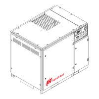
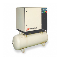
Do you have a question about the Ingersoll-Rand HP 15 and is the answer not in the manual?
Provides essential safety guidelines for operating and maintaining the air compressor unit.
Outlines critical safety measures to be followed before installation or maintenance.
Requirements for adequate ventilation for air-cooled compressors.
Specifies requirements for a suitable and level installation foundation.
Steps and precautions for connecting the compressor's electrical system.
Procedure to ensure correct motor rotation to prevent airend damage.
Instructions for pre-start checks, starting, and stopping the compressor unit.
Recommended maintenance intervals for keeping the compressor in good condition.
General precautions and tool requirements before performing maintenance.
Procedure for testing the pressure relief valve monthly.
Instructions for ensuring proper alignment of drive belts and sheaves.
Full voltage electrical schematic diagram for the compressor unit.
Star-delta electrical schematic diagram for the compressor unit.
Diagram illustrating the piping layout and components of the compressor system.
| Model | HP 15 |
|---|---|
| Maximum Pressure | 175 psi |
| Number of Cylinders | 2 |
| Phase | 3 |
| Cooling System | Air Cooled |
| Lubrication System | Splash Lubricated |
| Horsepower | 15 hp |


 Loading...