Do you have a question about the Ingersoll-Rand XP 15 and is the answer not in the manual?
General safety instructions for installing and operating the compressor.
Critical precautions to take before installing or performing maintenance on the compressor.
Specific warnings about high temperature shutdown, piping, and breathing air applications.
Essential considerations for plant air system piping and moisture control.
Steps and precautions for connecting the compressor's electrical system.
Pre-operation checks, starting, and stopping procedures for the compressor.
Details on the coolant system, its function, and components like filters and coolers.
Description of the air system components and their functions in air compression.
Recommended maintenance tasks and intervals for keeping the compressor in good condition.
Steps for ensuring proper alignment of drive and driven sheaves to prolong belt life.
Detailed steps for replacing worn shaft seals, typically at 8,000-hour intervals.
Procedure for draining, refilling, and checking the coolant level in the compressor.
Wiring diagram for the compressor's full voltage electrical system.
Wiring diagram for the compressor's star-delta electrical system.
Schematic showing the compressor's piping layout and component connections.
Detailed parts list for the main functional components of the compressor unit.
A comprehensive list of recommended spare parts for the compressor.
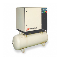
| Model | XP15 |
|---|---|
| Max Pressure | 175 PSI |
| Horsepower | 5 HP |
| Engine Type | Electric |
| Tank Size | 60 Gallons |
| Voltage | 230V |
| Phase | Single |
| Air Flow Rate @ 175 PSI | 15 CFM |
| Air Delivery @ 175 PSI | 15 CFM |
| Noise Level | 78 dB |