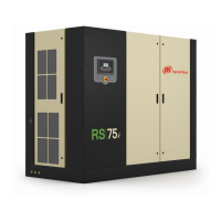
Do you have a question about the Ingersoll-Rand RS30i and is the answer not in the manual?
Provides basic information about the product.
Follow all danger, warning, caution, and operating instructions. Ensure labels are legible.
Inspect for damage, note any issues on the receipt, and contact the carrier.
Prepare for long term storage if not commissioned within six months.
Install in a dry, well-ventilated area, free of contaminants and noise.
Ensure proper piping, use filters, and install drain traps for condensate.
Qualified electrician shall perform all installations and service. Ensure proper grounding.
Ensure condensate drains are unimpeded and dispose of responsibly.
Standard package designed for indoor use, specific temperature ranges apply.
Dryer operation modes: default non-cycling and energy efficient.
Describes the controller's membrane, LCD display, command and navigation keys.
Indicates current status: OK, Warning, or Trip.
Keys for starting, stopping, loading, unloading, and resetting the compressor.
Explains the layout of the display screen: Folder Bar, Title Bar, Page Content, Dashboard.
Displays system overview, online/offline setpoints, and package discharge pressure.
Shows operational counters like power on hours, running hours, and starts.
Details analog inputs like pressure, temperature, and current.
Allows adjustment of setpoints like Online/Offline Pressure, Lag Offset, and Operation Mode.
Configure options like Auto-Restart, COM Control, and Scheduled Start/Stop.
Indicates failure or absence of sensors like 7ATT.
Alerts if sump pressure exceeds rated pressure plus limit.
Occurs if discharge pressure exceeds maximum offline pressure.
Indicates required maintenance based on operating hours.
Indicates dryer condenser or evaporator temperature switch activation.
Trip occurs if sump pressure is below limit for a specified duration.
Trip occurs if airend discharge temperature exceeds threshold.
Trip occurs if motor rotation is incorrect or fails to establish.
Conditions that prevent the compressor from starting.
Displays the status of filters: OK or Change required.
Set service intervals and reset maintenance counters.
Configure language, units, and backlight settings.
Adjusts the brightness of the controller display.
Interface the controller to a Modbus RTU master via RS-485 cable.
Guidelines for routing RS-485 cables to avoid electrical interference.
Assign a unique address to each compressor connected to the Modbus network.
Set the RS-485 address for each compressor in the X-Series network.
Configure COM control and Auto-Restart for system controller interaction.
| Model | RS30i |
|---|---|
| Type | Rotary Screw |
| Power | 30 hp |
| Voltage | 460V |
| Phase | 3 |
| Flow Rate | 125 CFM |
| Max Pressure | 125 psi |


