80447113 Rev.A 9
MAINTENANCE
MAINTENANCE SCHEDULE
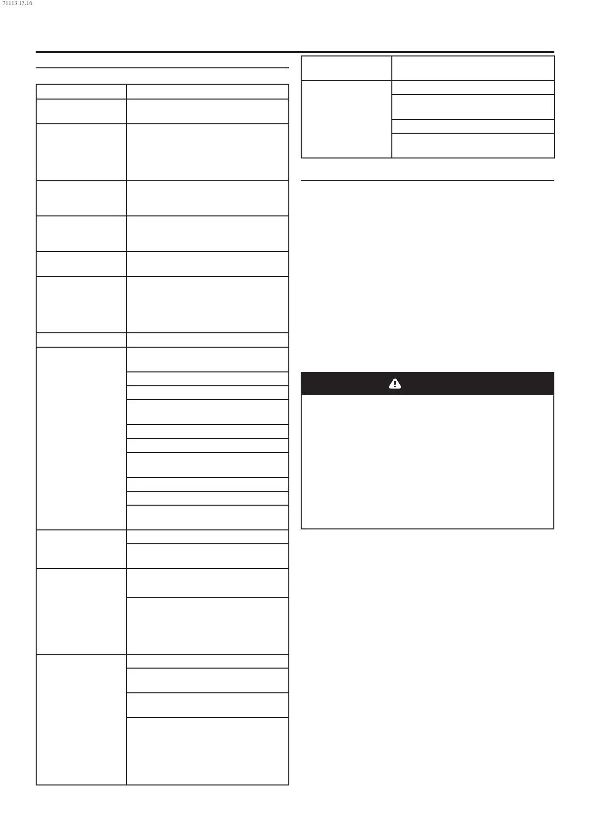
UP SERIES MAINTENANCE SCHEDULE
PERIOD MAINTENANCE
Each 24 hours opera-
tion
Check the coolant level and replenish if
necessary.
Visual check of
machine for any
leaks, dust build up
or unusual noise or
vibration
Report immediately, contact Ingersoll
Rand authorized distributor for assist-
ance if in doubt.
When compressor is
receiver mounted
Drain air receiver of condensate, or check
that automatic drain is operating.
Visual check condi-
tion of package
pre-lter
Blow clean if needed.
First 150 hours Change the coolant lter.
Each month or 100
hours
Remove and clean package pre-lter,
replace if needed Check the cooler(s)
for build up of foreign matter.Clean if
necessary by blowing out with air or by
pressure washing.
Every 1000 hours Analyze food grade lubricant (Ultra FG)
Each year or 2000
hours
Check the operation of the high tempera-
ture protection switch (109˚C).
Replace elements in IRGP and IRHE lters.
Change the coolant lter.
Check scavenge screen for blockage,
clean if required.
Change the separator element.
Change the Air Filter element.
Take coolant sample for uid analysis
(Ultra/Ultra EL).
Change the package pre–lter.
Check Drive Belts.
Motors with grease ttings-grease per
motor data TAG
Every 6000 Hours Replace food grade lubricant(Ultra FG).
Check and replace all items included
within 2000 hour service.
1 year external and
6 years internal pres-
sure vessel inspec-
tion. Frequency may
be otherwise dened
by local or national
legislation.
Separator vessel and air receiver when
tted
Fully inspect all external surfaces, and
ttings. Report any excessive
corrosion, mechanical or impact damage,
leakage or other
deterioration.
Every two years or
8000 hours
Change drive belts.
Replace Premium Coolant (Ultra) at
whichever interval occurs rst.
Check and replace all items included
within 2000 hour service.
Fit the following reconditioning parts as
appropriate:
Solenoid valves
Inlet valve kit
Minimum Pressure valve kit
Thermostatic Valve Kit
16000 hours or every
3 years
Replace Extended-life Premium Coolant
(Ultra EL)
Every 4 years or 16000
hours
Replace all hoses.
Strip, clean and re–grease motor bearings
on motors with grease ttings
Fit replacement electrical contactor tips.
Motors without grease ttings - replace
sealed bearings
ROUTINE MAINTENANCE
This section refers to the various components which require
periodic maintenance and replacement.
It should be noted that the intervals between service
requirement may be signicantly reduced as a consequence
of poor operating environment. This would include eects of
atmospheric contamination and extremes of temperature.
The SERVICE/MAINTENANCE CHART indicates the
various components’ descriptions and the intervals when
maintenance has to take place. Oil capacities, etc., can be
found in the PRODUCT INFORMATION SHEET.
Compressed air can be dangerous if incorrectly handled.
Before doing any work on the unit, ensure that all pressure
is vented from the system and that the machine cannot be
started accidentally.
Before beginning any work on the compressor, open,
lock and tag the main electrical disconnect and close
the isolation valve on the compressor discharge.
Vent pressure from the unit by slowly unscrewing the
coolant ll cap one turn. Unscrewing the ll cap opens
a vent hole, drilled in the cap, allowing pressure to
release to atmosphere. Do not remove the ll cap until
all pressure has vented from the unit. Also vent piping
by slightly opening the drain valve. When opening the
drain valve or the coolant ll cap, stand clear of the
valve discharge and wear appropriate eye protection.
Ensure that maintenance personnel are properly trained,
competent and have read the Maintenance Manuals.
Prior to attempting any maintenance work, ensure that:-
all air pressure is fully discharged and isolated from the
system. If the automatic blowdown valve is used for this
purpose, then allow enough time for it to complete the
operation.
the machine cannot be started accidentally or otherwise.
all residual electrical power sources (mains and battery)
are isolated.
•
•
•
71113.13.16
 Loading...