IDS400 INSTALLER MANUAL NO. 700-204-02A ISSUED NOV 2000 VER 1.01 7
IDS400 INSTALLER MANUAL
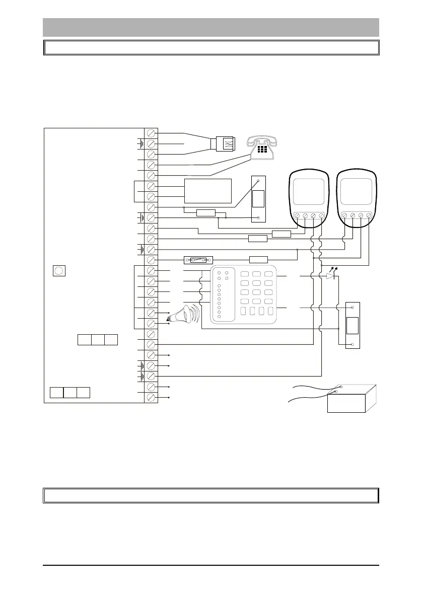
2. Installation and Wiring
Please refer to Figure 1: Connection Diagram and familiarise yourself
with the following sections.
Figure 1: Connection Diagram
v All zones are end-of-line supervised. Any unused zones must also
be terminated with the appropriate resistor.
v The end of line resistor should be placed inside or as close to the
sensor as possible.
3. Connecting the Telephone Communicator
Refer to Figure 1.
v The integral communicator has built in lightning protection to
protect it from lightning induced transients. For optimum
NC C
+
-
P.I.R.
P
A
N
I
C
Line
Line
Phone
Zone 4
Zone 3
Zone 2
Zone 1
+
C
D
Keypad
+
_
_
Siren
+
+
12V
+TX
18V AC
Radio
Transmitter or
Communicator
Auxilliary Outputs
1
2
3K3
NC C
+
-
P.I.R.
3K3
3K3
3K3
123
4
56
789
0
*
#
P
M
O
D
E
ZONE 1
ZONE 2
ZONE 3
ZONE 4
ZONE 5
ZONE 6
ZONE 7
ZONE 8
FM
GND
CK
DAT
+12V
P
A
N
I
C
LED
PAN
B
L
A
C
K
W
IR
E
R
E
D
W
I
R
E
-
+
12V BATTERY
Panic
Button
N/O
MAG SW N/C
Door LED
Panic
Button
N/O
NOTE:
No end-of-line
resistor
Radio Transmitter/
Communicator Power
Connect to mains
Transformer
SW1
Hardware
Reset
Switch
FU2 Auxilliary
Power Fuse
1 AMP
FU1 Battery
4 AMP
Earth
Telkom
Phone
 Loading...