8 IDS400 INSTALLER MANUAL NO. 700-204-02A ISSUED NOV 2000 VER 1.01
IDS400 INSTALLER MANUAL
protection connect a low impedance earth to the communicator. A
poor earth will be ineffective and may result in damage to the
communicator and alarm panel.
v Always connect the telephone communicator in the line seizure
mode. Never in parallel with the telephone.
v If a radio transmitter or voice message communicator is being
used for monitoring purposes the power for these devices should
be taken from the “+TX” terminal.
NOTE:
The TX+ terminal is protected by means of the battery fuse. If
excessive current (2 amps max) is drawn from this terminal,
battery power to the alarm may be lost.
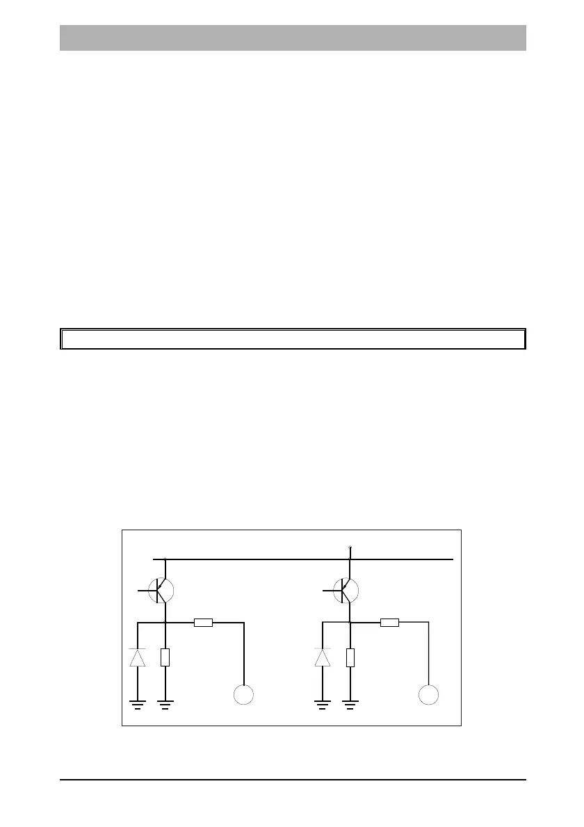
4. Programmable Outputs
A relay board must be used when any device requiring a high current
is connected to a programmable output. The current sink and source
capability is the same for outputs 1 and 2. The output circuitry
consists of a 12 volt source with a 56Ω series resistor. Current sink is
via a 1000Ω resistor to negative. The represented output circuit is
provided in Figure 2 below.
Figure 2: Programmable Output Configuration
12V
56R
1000R
GND
Output 2
56R
1000R
GND
Output 1
 Loading...