UM_INAP375R Revision 1.2_A1 Inova Semiconductors Confidential Page 10 of 37
User Manual
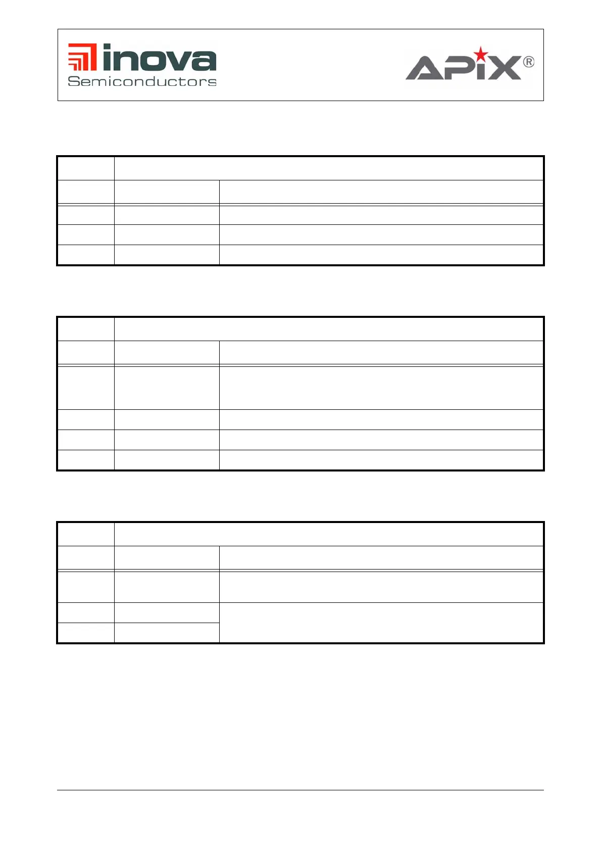
3.1.6 Connector and interface pin description
JP5 ISP UART Interface
Pin Signal Description
1 RXD1 Receive data for ISP
2 TXD1 Transmit data for ISP
3 GND Signal ground
Table 3-1: ISP UART Interface
SV1 Power supply for extension boards
Pin Signal Description
1,3,5,7,9,
11,13,15,
17,19
GND Signal ground
2,4 12V0 9V - 18V for extension board’s DC/DC converter
14,16 DCDC_3V9 3.9 V Supply for extension board’s 3.3V LDOs
18,20 DCDC_2V1 2.1 V Supply for extension board’s 1.8V LDOs
Table 3-2: Extension board supply
SV2 APIX2 I2C, SPI slave and GPIO interface
Pin Signal Description
2,4,6,8,10
,12,14,16
GND Signal ground
1 AX_I2C_SCL
APIX2 I2C master interface
3 AX_I2C_SD
Table 3-3: APIX2 I2C, SPI slave and GPIO interface
 Loading...