UM_APIX2_ADK_TX (Rev2) Revision 1.2_A1 Inova Semiconductors Confidential Page 25 of 37
User Manual
The connectors SV1, SV2, X1 and X2 need to be connected through specific cables provided with the kit to the
master boards.
Dip Switch S1 needs to be set to 00011000 ([8:1]).
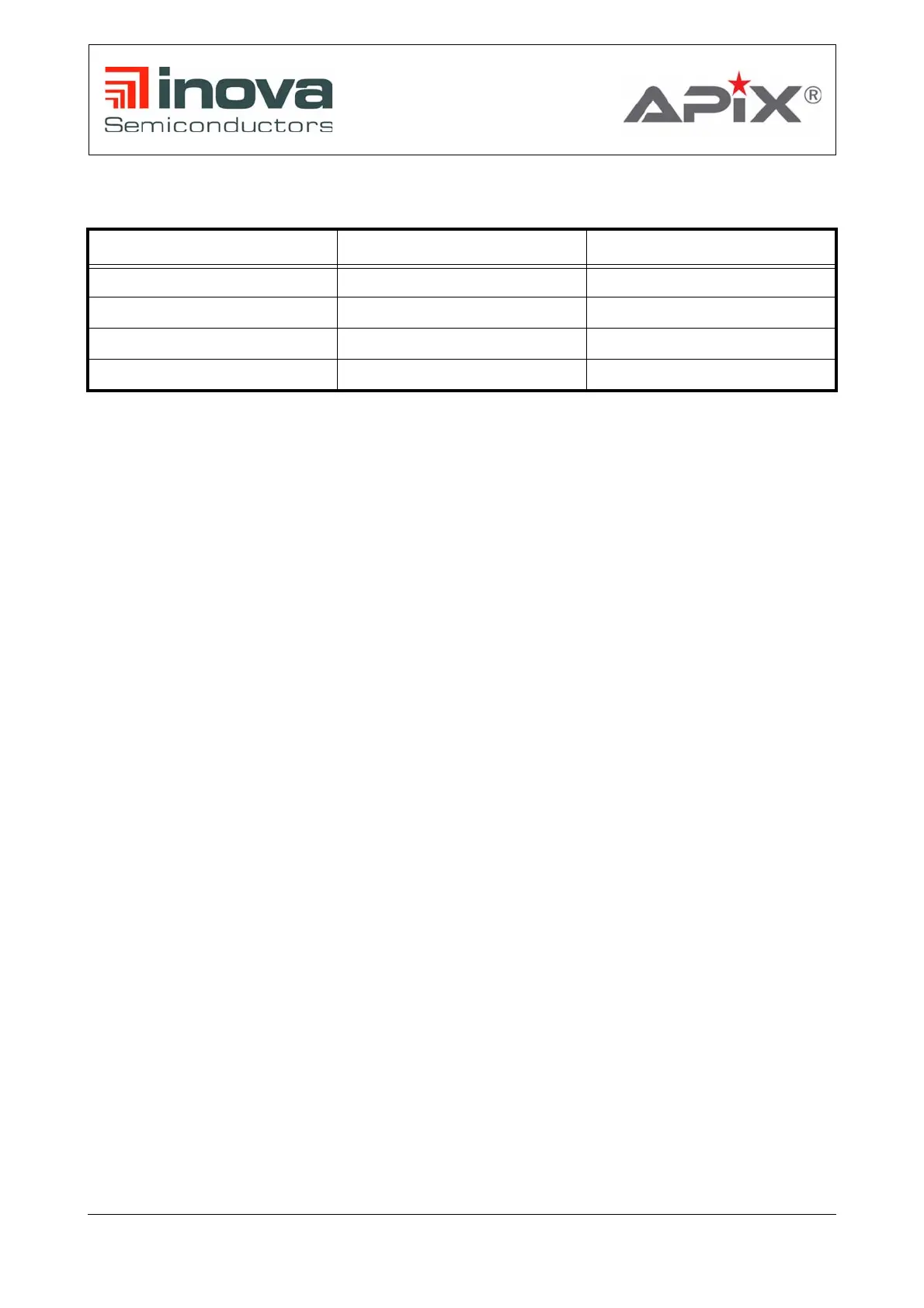
Master board connector Ethernet board connector Description
SV1 SV1 Power supply
SV2 SV2 Control signals
X5 X1 Data lines
X6 X2 Data lines
Table 6-2: Interconnect between Ethernet and Master board
 Loading...