Do you have a question about the Inovance GL20-4DA and is the answer not in the manual?
Introduces the scope of the user guide for the GL20-4DA analog output module.
Provides information on related documentation like the GL20-RTU-ECT Communication Interface Module User Guide.
Lists past versions and dates of the manual, including minor corrections and first release.
Explains how to download the PDF version of the user guide from the Inovance website or via QR code.
Outlines the warranty period, terms, and conditions for product repair or replacement.
Lists essential safety rules for operating, installing, and maintaining the equipment.
Defines hazard levels like Danger, Warning, and Caution to ensure user safety.
Provides critical safety guidance for designing control systems involving the module.
Warns about the installation process, emphasizing the need for trained personnel and proper electrical disconnection.
Details safety precautions for wiring, including potential hazards like electric shock and proper installation practices.
Provides cautions for operating and maintaining the module safely, avoiding contact with live terminals.
Advises on the proper disposal of the product as industrial waste, following environmental regulations.
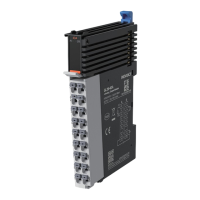
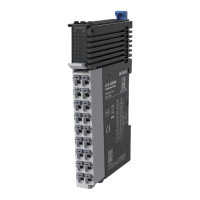
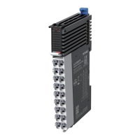
Explains the components of the product's model number and the information found on its nameplate.
Describes the PR (Power/running) and ERR (State machine error) indicators on the module.
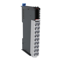
Refers to the terminal definitions for detailed explanations of the module's connection points.
Explains the color coding used on the module for identifying different types of I/O signals.
Details the input voltage and current requirements for the module's power supply.
Lists the technical specifications for the module's analog output, including range, resolution, and accuracy.
Outlines the configurable software parameters for the module, such as conversion modes and sampling settings.
Provides the physical dimensions of the module for installation planning and space requirements.
Illustrates how to connect cables to the module, showing the overall layout and cable management.
Details the procedures for installing modules side-by-side and mounting the module onto a DIN rail.
Explains the step-by-step process for safely removing the module from the DIN rail using a screwdriver.
Provides guidance on selecting appropriate cable lugs and diameters for connecting the module.
Lists the terminals on the module and their corresponding signal assignments for proper wiring.
Describes wiring precautions and provides diagrams for voltage and current controlled signal connections.
Guides on how to add the GL20-4DA module to the project environment, showing the software interface.
Explains how to configure the module's channels, enabling access and setting parameters like conversion mode.
Illustrates defining variables for each channel using ST programming language within the software.
Shows how to map the defined variables to the module's channels in the network configuration interface.
Instructs on compiling, downloading, and running the project after configuring and mapping the module.
| Input Voltage | 24 V DC |
|---|---|
| Type | Analog Output Module |
| Number of Analog Outputs | 4 |
| Output Type | Voltage/Current |
| Resolution | 12-bit |
| Isolation | 1500 VAC |
| Communication Interface | RS-485 |
| Communication Protocol | Modbus RTU |
| Mounting Type | DIN Rail |
| Output Range | 0-20 mA / 0-10 V |
| Accuracy | ±0.1% F.S. |
| Operating Temperature | -10°C to 55°C |
| Storage Temperature | -20°C to 70°C |
| Humidity | 5% to 95% RH, non-condensing |
| Weight | 150 g |