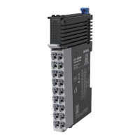
The GL20-1600END is a 16-channel digital input expansion module designed by Inovance, supporting both sourcing and sinking input types. It is intended for use with PLC masters, such as the Easy series, and is part of the GL20 series of general local modules. The module is identified by the product code 01440291 and is compatible with AC800 series and Easy series PLCs.
Function Description:
The GL20-1600END module serves as a digital input interface, allowing a PLC system to receive 16 digital signals. It supports both sourcing and sinking input modes, providing flexibility in connecting various types of sensors and input devices. The module is designed to expand the I/O capabilities of a PLC, enabling the monitoring of a larger number of digital inputs in industrial automation applications. Each input channel has an associated indicator for visual feedback on its active state.
Important Technical Specifications:
Power Supply Specifications:
- Rated bus input voltage: 5 VDC (ranging from 4.75 VDC to 5.25 VDC)
- Rated bus input current: 100 mA (typical at 5 VDC)
- Rated terminal input/output voltage/current: Not applicable (N/A)
- Hot swap: Not supported
- Input type: Digital input
- Input mode: Sinking/Sourcing
- Input channels: 16
- Input voltage class: 24 VDC ±10% (ranging from 21.6 VDC to 26.4 VDC)
- Input current (typical): 4 mA (typical at 24 V)
- ON voltage: >15 VDC
- OFF Voltage: <5 VDC
- ON/OFF response time: 100 µs/100 µs
- Software filter time: Supported
- Input impedance: Reference: 5.3k to 5.6k
- Isolation: Yes
- Input action display: Input indicators are turned ON (via software control) when the inputs are in the driving state.
- Input derating: 75% derating at 55°C (when the number of ON inputs does not exceed 12), or 10°C derating when all inputs are ON.
Software Specifications:
- Software input filter time: Options include Without filter, 0.25 ms, 0.5 ms, 1ms (factory setting), 2 ms, 4 ms, 8 ms, 16 ms, and 32 ms. Two filter time parameters can be set, each for a group of 8 channels.
- Input port anomaly detection and indication: N/A
- Input channel logic level configuration: Not supported
- Independent channel enable configuration: Not supported
- Diagnostic report configuration: Not supported
- When in stop mode: Outputs are not refreshed, inputs can be refreshed when in state SAFE-OPERATIONAL.
- I/O mapping: Supports bitwise, bytewise, and wordwise addressing.
Mechanical Dimensions:
- Width: 82 mm
- Height: 100 mm
- Depth: 105.5 mm (including mounting hook)
- DIN rail installation position: 5mm below the module center.
- Space requirement: At least 10 mm space above the module for mounting hook movement.
Usage Features:
Installation:
- Side-by-Side Installation: Multiple modules can be installed side-by-side using top and bottom guides.
- DIN Rail Mounting: The module aligns with a DIN rail and locks into place with an audible click. A DIN rail mounting hook automatically moves downward to secure the module. If it doesn't, the hook should be pressed down to ensure proper installation.
- End Plates: End plates should be mounted on either side of the module assembly by hooking the bottom to the DIN rail, rotating to hook the top, and tightening a screw to lock them.
- Cable Connection: The manual provides guidance on cable lug and diameter selection, with recommended options from KST and Suzhou Yuanli. Specific crimping requirements for tubular lugs are detailed, including dimensions (8-10mm strip length, Max2.0mm and Max2.5mm crimp diameters).
Wiring:
- Terminal Definition: A detailed table maps left and right indicators to signals and terminals (e.g., DI0 to A1/B1, DI10 to A1/B1).
- Terminal Wiring Diagram: The module features an internal circuit with optocoupler insulation for each input channel, supporting both sink and source input configurations with a 24VDC power supply.
Programming:
- Module Addition: The GL20-1600END module must be added to the PLC project (e.g., using AC802 as the master control module).
- Filter Time Configuration: Input filter times for each channel can be configured via the "Channels Config" interface, with options ranging from "Without filter" to 32 ms. Two filter time parameters can be set, each for a group of 8 channels.
- Variable Mapping: Digital inputs can be mapped to variables (e.g., CHO, CH1) defined in the PLC program using ST (Structured Text) programming language. This allows the PLC to read and process the input signals.
- Project Download and Run: After compiling the project, it can be downloaded to the PLC and executed.
Safety Instructions:
- General Precautions: Users must read and comply with safety instructions during installation, operation, and maintenance. All safety marks on the product and in the document must be followed. Inovance is not responsible for injuries or damage due to improper use.
- Safety Levels: The manual defines "Danger," "Warning," and "Caution" to indicate potential risks, from severe personal injuries or death to minor injuries or equipment damage.
- Control System Design:
- A safety circuit external to the PLC is required to ensure safe operation in case of external power failure or PLC fault.
- Fuses or circuit breakers are necessary to prevent smoke or fire from overcurrent or short-circuits.
- Emergency stop, protection, and interlocked circuits must be set in external PLC circuits.
- External protection circuits and safety mechanisms should be designed for output signals that could cause critical accidents.
- Appropriate external control circuits are needed to ensure normal operation, as PLC outputs may not be controllable if a fault occurs in the controller circuit.
- The PLC is designed for indoor electrical environments (overvoltage category II), and the power supply must have a system-level lightning protection device.
- Installation Safety:
- Installation must be performed by specialists with electrical training.
- All external power supplies must be disconnected before removing/installing the module to prevent electric shock or malfunction.
- The PLC should not be used in environments with dust, oil smoke, conductive dust, corrosive or combustible gases, high temperature, condensation, wind & rain, vibration, or impact.
- The PLC is open-type equipment and must be installed in a locked control cabinet with IP20 protection.
- Wiring Safety:
- Wiring must be performed by trained personnel.
- All external power supplies must be disconnected before wiring.
- The terminal cover must be installed before power-on.
- Good insulation on terminals is crucial to maintain insulation distance between cables.
- Power supply must be cut off before connecting the product.
- The input power must be stable 24 VDC ±20% to prevent damage.
Maintenance Features:
Maintenance and Inspection:
- Personnel: Maintenance and inspection must be carried out by personnel with necessary electrical training and experience.
- Power On/Off: Do not touch terminals while power is on. Disconnect all external power supplies before cleaning the module, re-tightening screws, or removing/connecting communication wirings.
- Environmental Protection:
- Prevent metal filings and wire ends from dropping into ventilation holes during installation.
- Ensure no foreign matters are on ventilation surfaces to prevent poor ventilation, fire, or malfunction.
- Ensure the module is securely connected to its connector and hooked firmly to prevent malfunction or fall-off.
Warranty and Disposal:
- Warranty Period: The product has an 18-month warranty from the date of manufacture (indicated by the barcode). Maintenance fees apply after this period, or for damages caused by non-recommended functions, use outside intended scope, or force majeure events.
- Disposal: Scrapped products should be treated as industrial waste. Batteries must be disposed of according to local laws. Retired equipment should be recycled following industry disposal standards to prevent environmental pollution.