Chapter: Installation
4-2 M10-16250-EN
.
4. Rotate the spirit level 90° to verify that the load frame is level side to side and front to
back.
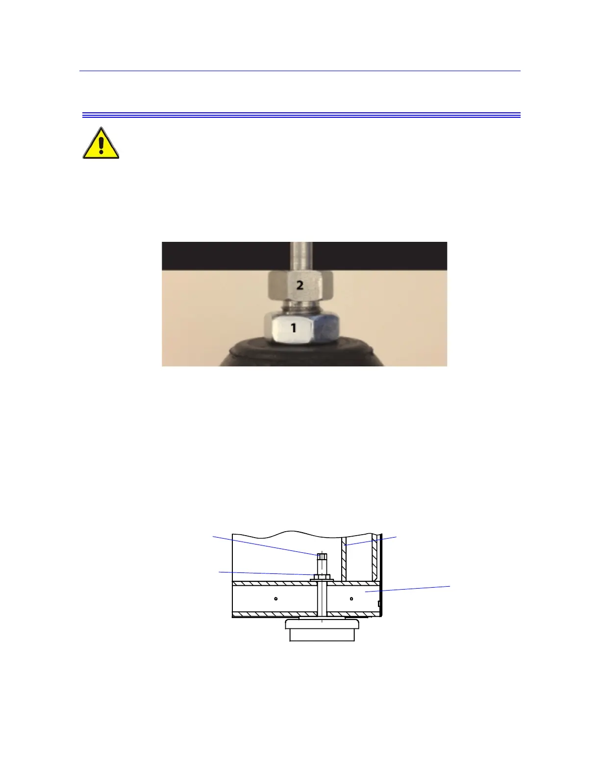
5. When the machine is level, tighten the lock nut on each leveling foot.
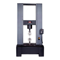
Procedure for 5988 and 5989 Load Frames
The procedure for 5988 and 5989 load frames is the same in principle as for the other floor
model frames. However, as shown in Figure 4-2 on page 4-2, the lock nut and hex nut for
adjustment is above the frame base. You must therefore remove the front and rear covers
from the machine to expose these nuts.
As you make adjustments, make sure no more than 12mm (0.5in) of thread is
exposed. If you expose more thread, there is a risk that the threaded adapter can
separate from the foot.
Figure 4-1. Adjusting a Leveling Foot
Figure 4-2. Leveling Foot on 5988 and 5989 frames
Frame base
Loosen the lock nut
Turn hex nut to adjust level