Chapter: Introduction
1-2 M10-16250-EN
System Description and Terminology
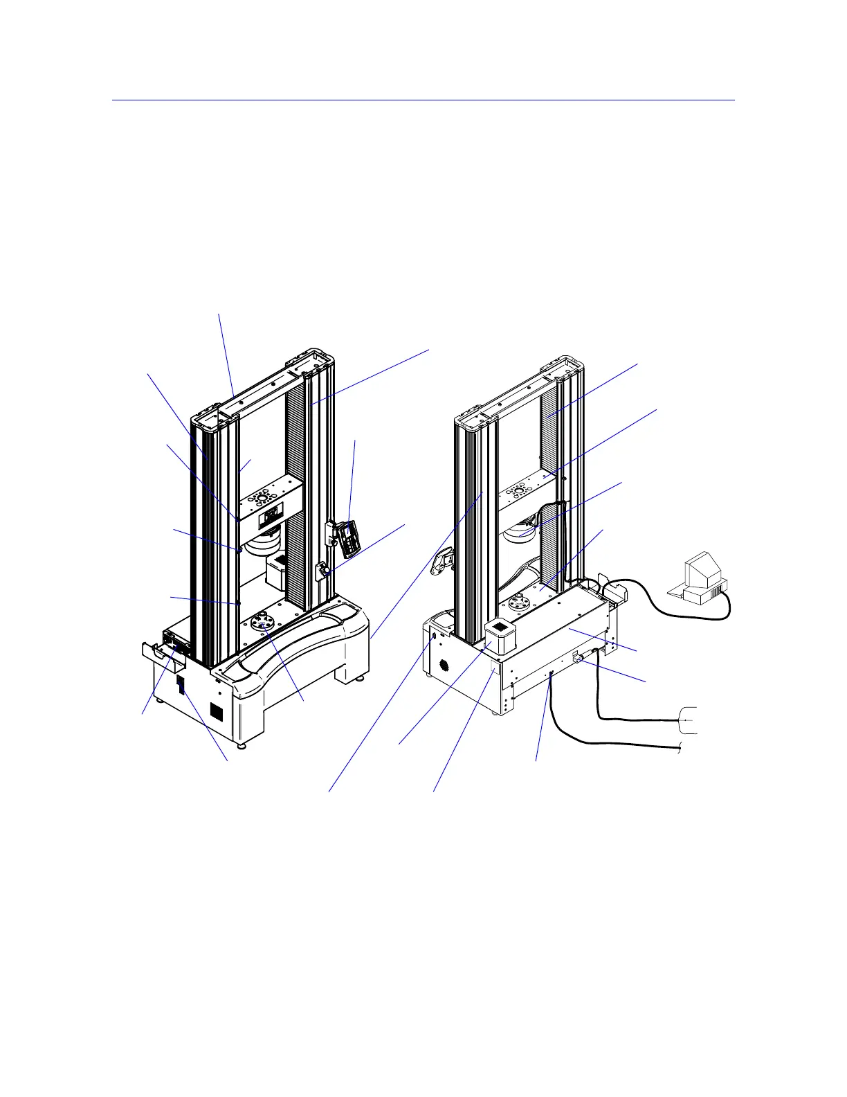
Figure 1-1 on page 1-2 shows the location of components on 5982, 5984 and 5985 load
frames. The 5988 and 5989 frames are substantially the same, except for the location of the
power input and ground stud, as shown in Figure 1-2 on page 1-3.
Front View Rear View
Figure 1-1. 5982, 5984 and 5985 Dual Column Floor Frames
Frame base
Base
Base adapter
Controller
Options panel
Motor cover
Ground stud
Column
cover
T-slots
Ballscrew cover
Crosshead
Top plate
Emergency stop
button
Power switch
Control
panel
beam
System ID label
(5982 only)
Upper
Limit
switch
actuator
Limit
switch
rod
limit
switch
Lower
limit
switch
Load cell
Power input