Chapter: Introduction
1-4 M10-16250-EN
Special fixtures are available for applications such as flexure and peel testing. For strain
measurement, an optional strain gauge extensometer attaches to the specimen. You can use
non-contacting extensometers with specimens that are unable to support a contacting
extensometer. Contact your regional Instron office or check our web site at
www.instron.com
for assistance with Instron’s grips and fixtures.
The following table defines the components of the testing system:
Principle of Operation
The system communicates primarily through the controller. The controller contains sensor
conditioning cards for the system transducers and transfers data between the transducers and
the computer. The controller also communicates with the load frame via a frame interface
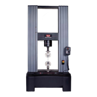
Table 1-1. Testing System Components
Component Description
Load Frame The load frame comprises a base, one or two columns, a moving
crosshead, and a top plate. It is a high stiffness support structure
against which the test forces react.
Each column comprises a guide column and a ballscrew. The
crosshead is mounted on both the guide column and the ballscrew.
Rotation of the ballscrew drives the crosshead up or down while the
guide column provides stability.
Controller The hardware that controls the frame and any ancillary equipment
connected to the testing system. The controller panel contains all the
connectors for load cells, extensometers and any other sensors that
are required for testing.
Control Panel The hardware panel, mounted on the side of the load frame, that lets
you perform some of the software functions directly at the frame.
Load String Comprises all of the components that you install between the moving
crosshead and the load frame base (or fixed crosshead). Typically
this involves a load cell, a set of grips, any adapters that are required
to connect the components, and the specimen to be tested.
Typically, you mount a load cell on the crosshead, then a pair of grips
or fixtures on the load cell and frame base. The grips or fixtures
secure the specimen and when you start a test the crosshead moves
up or down applying a tensile or compressive load to the specimen.
The load cell converts this load into an electrical signal that the
software measures and displays.
Bluehill Software Instron testing software that controls the testing system, running tests
and analyzing test data to produce test results.
Specimen A single piece of material to be tested.