20
15. ELECTRICAL CONNECTIONS
Before connecting the unit to the electrical supply, make sure that the electrical board is in good
conditions and please follow the following recommendations:
§ Consult the electrical schema supplied by manufacturer.
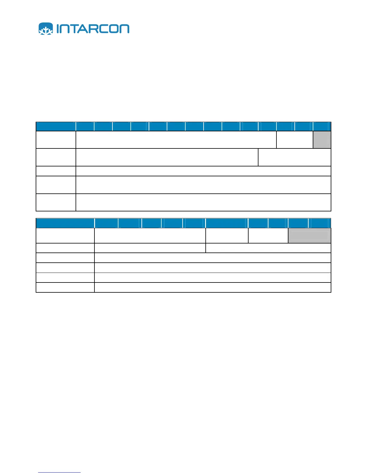
§ Only use electrical cables of the appropriate characteristics and capacity according to the following
table. Notice that single phase units have a three-wire supply and three phase units have a five-
wire supply, being always the ground wire in green-yellow colour.
MCV - MCR 0008 0010 0012 1010 1012 1014 1016 1018 1024 2024 2026 2034 3034 3038
Power supply
220-I-50
2 x 1,5 mm² + T
T
Power supply
400-III-50
4 x 1,5 mm² + T
Cold room light
2 x 1 mm² + T
Door
microswitch
2 x 1 mm²
Remote
controller
2 x 1 mm²
BCV - BCR 0018 1018 1026 1034 2034 2054 2074 3074 3086 3096
Power supply 220-I-50
2 x 1,5 mm² + T
2 x 2,5 mm² +
T
2 x 4 mm² +
T
Power supply 400-III-50
4 x 1,5 mm² + T
Cold room light
2 x 1 mm² + T
Door microswitch
2 x 1 mm²
Remote controller
2 x 1 mm²
Power supply 220-I-50
2 x 1 mm²
§ Always install the appropriate protection device on the supply line. In case that more than one unit
is installed, always provide separate protection devices for each of the installed units.
§ Electrical wires section in power supply wiring is to be calculated according to the electrical data
provided by manufacturer in data plate, power supply wires length, wires type, etc.; always
according to electrical regalement.
§ Optionally install a door switch on the end of the supplied cable or close the end of the cable.
§ Install the room light in the supplied cable.