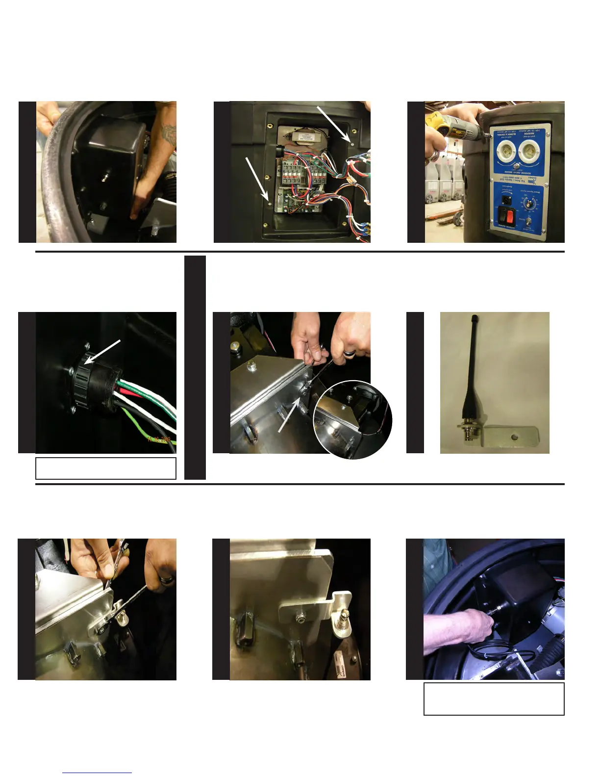
Support the back of the electrical
box as shown.
While supporting the electrical box
align holes and install the (2) #6
screws from step 4 using a #2 Phil-
lips screw driver.
Once the electrical box is secured
to the base, re-attach the electrical
panel to the base using the (6) #8
screws from step 3.
Align circular connector to ange
receptacle on electrical box. Turn
the outer ring of the circular con-
nector clock-wise until it stops.
OUTER RING
TURN CLOCKWISE
TO TIGHTEN
Note: Outer ring of connector will not
tighten unless properly aligned!
At the airlock locate and remove
the 1/4” bolt as shown below using
(2) 7/16” open end wrenches.
Attach the antenna mount as
shown below using the same 1/4”
bolt & nut.
1/4” bolt
At this point, antenna mount should
be secure as shown.
Locate antenna mount as shown.
Attach one end of the cable to the
antenna mount on the electrical
box, as shown.
S
T
E
P
49
S
T
E
P
50
S
T
E
P
51
S
T
E
P
52
S
T
E
P
53
S
T
E
P
54
S
T
E
P
55
S
T
E
P
56
S
T
E
P
57
Note: When attaching cable, you will need
to align the connector, push in and turn
clockwise.
Antenna Section