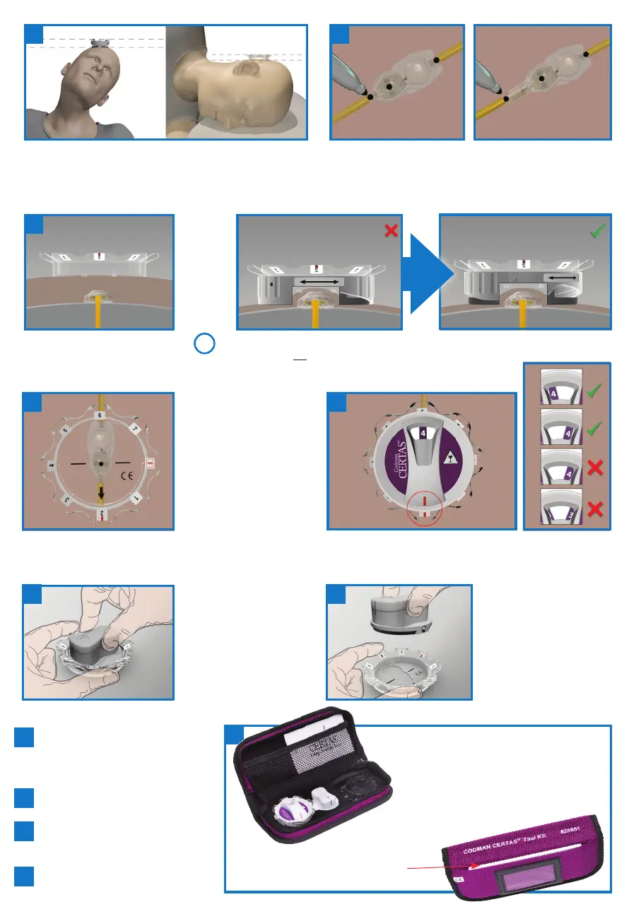
Locate the valve by palpation. Mark the center of the valve mechanism
and the inlet and outlet connector barbs.
Select the appropriate Locator Tool (based on tissue thickness). It should be stable and with the tissue just below the valve cut-out.
Adjustable Height Locator Tool
Tissue should not protrude through valve cut-out.
Place Locator Tool atop the
implanted valve:
• black lines are aligned
with the marked
center of the hard valve
mechanism
• direction of flow arrow
aligned with the catheter
barb marks
Repeat Steps 4 and 5 to confirm
successful adjustment of the
performance seing. Always confirm the
desired performance seing of the valve.
If the desired performance seing is not
achieved, repeat Steps 6 through 8.
It is recommended to record the valve
seing in the patient’s record and I.D.
wallet card.
Disinfect the tool kit components.
Position the patient so that the implanted
valve is horizontal.
Insert the Adjustment Tool
into the Locator Tool with the
arrow pointing to the current
performance seing. Holding the
“petals” of the Locator Tool,
turn the Adjustment Tool until
the arrow points to the desired
performance seing.
Li the Adjustment Tool
from the Locator Tool straight
upwards a minimum of 3
cm (1.25 in.) then move it
horizontally away to avoid
inadvertently changing the
valve seing.
6
8
9
10
11
2
with SiphonGuard
®
Anti-Siphon Device
3
4
To determine the current valve seing, fully seat the Indicator Tool
into the Locator Tool with red markings aligned. Remove the
Indicator Tool.
5
Return all tools to their proper locations in the
storage case to prevent damage. Note: place
the Low Profile Locator Tool under the elastic
webbing in the boom of the storage case and
fully collapse the Adjustable Height Locator Tool.
12
Low Profile Locator Tool if thick
tissue or edema is present (>10 mm
above the valve).
7
1
or
Please consult the Instructions for Use for
more detailed information and appropriate
use of the devices.