
H
Heidi PerryAug 4, 2025
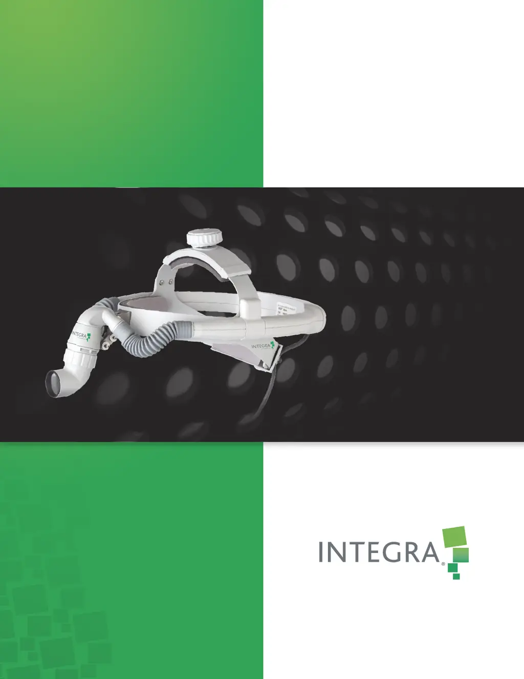
Why does the brightness of my Integra Medical Equipment spot decrease during use?
- Ssandra89Aug 4, 2025
If the brightness of the Integra Medical Equipment spot decreases during use, it might be because the LED temperature has increased due to blocked airflow. To resolve this, turn off the headlight and inspect the headlight module and controller fan vents for any obstructions. Remove any blockage you find.


