Model No: 3391 Drawring No:
Customer :
Model No:
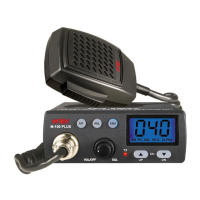
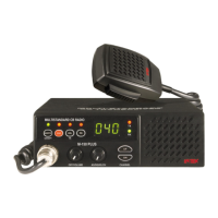
M-790 Plus
Rev,Date:
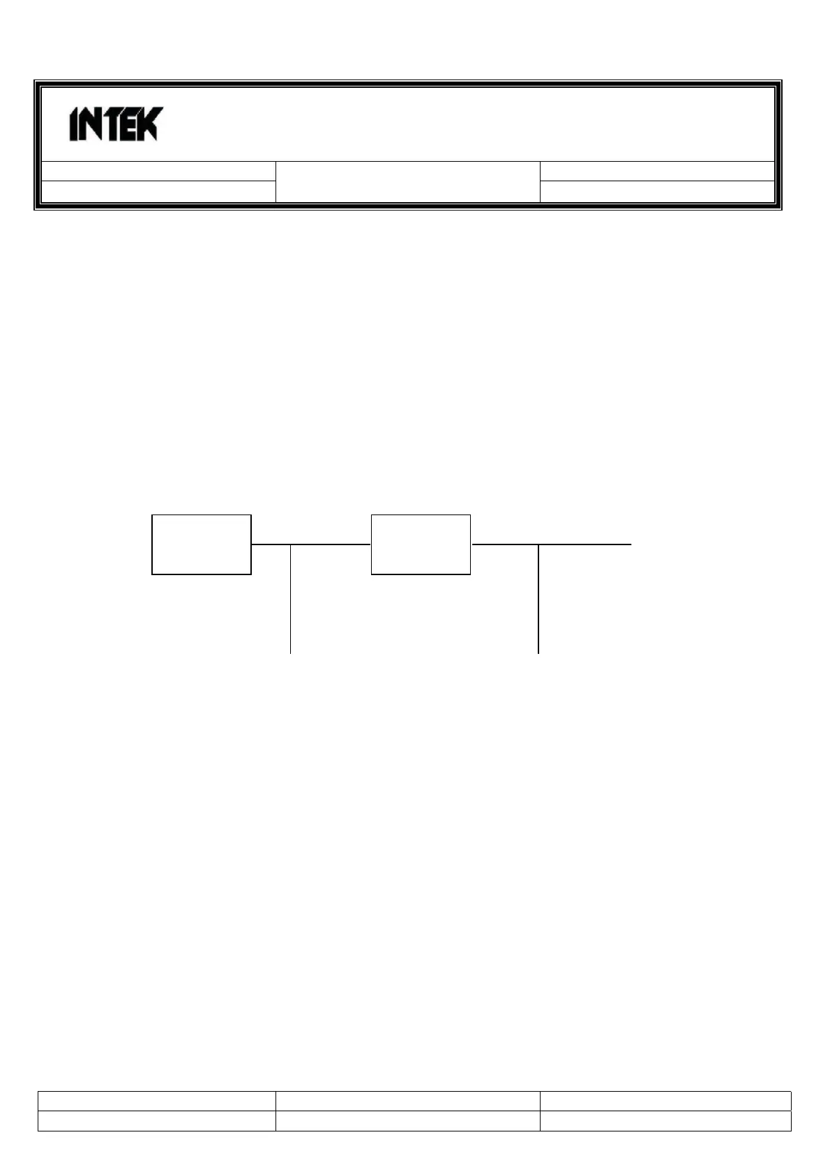
PLL CIRCUIT BLOCK DIAGRAM
1. INTRODUCTION
The frequencies for transmitter and receiver first local frequencies are all derived from a single 4.5 MHz
crystal by means of a phase locked loop. The first local oscillator frequencies are 16.270 MHz (CH 1) to
16.710 MHz (CH 40) for EU and 16.90625 MHz (CH 1) to 17.29625 MHz (CH 40) for UK . The second
local frequency is fixed at 10.240 MHz to generate second IF 455 KHz. During transmit, The VCO of
the PLL operates 13.4825 MHz (CH 1) to 13.7025 MHz (CH 40) for EU ,13.800625 MHz (CH 1) to
13.995625 MHz (CH 40) for UK the VCO frequency gose to the double circuit Q301,L301,L302 which
doubles the frequency to generate 26.965 MHz (CH 1) to 27.405 MHz (CH 40) for EU and 27.60125
MHz (CH 1) to 27.99125 MHz (CH 40) for UK
13.4825 MHz (CH 1) EU 26.965 MHz (CH 1)
13.7025 MHz (CH 40) EU 27.405 MHz (CH 40)
13.800625 MHz (CH 1) UK 27.60125 MHz (CH 1)
13.995625 MHz (CH 40) UK 27.99125 MHz (CH 40)
The VCO operating frequency for the receiver is 16.270,16.90625 MHz (CH 1) to 16.710,17.29625 MHz
(CH 40) as the first local oscillator, injected through the buffer AMP Q506 into the first fed balanced
mixer Q107,Q108
Created by: Approved by: Rev.No:
For Stage: Release Date: Page: 17 / 61
Q408
VCO
Q 301
Doubler
To Transmitter