Model No: 3390 Drawring No:
Customer :
Title
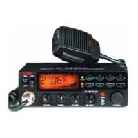
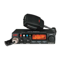
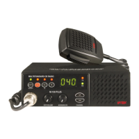
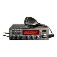
M-490 Plus
Rev,Date:
TRANSMITTER SECTION
Test Equipment Required
•
RF power meter (RF SSVM)
•
DC power supply (13.2 volt, 3 amp)
•
50 ohms dummy load (non-inductive)
•
Spectrum analyzer
•
RF attenuator (50 ohms non-inductive)
•
Frequency counter
•
Oscilloscope
•
Coupler
•
Audio generator
ALIGNMENT PROCEDURE
Step Setting
Connection Adjuster Adjust for
1
RF power stage
MIC : Transmit
Volume : optional
Squelch : optional
CH : selector : 19
CH9 : OFF
Connect dummy load
and RF power meter to
the EXT-ANT jack on the
set (Figure 3).
L301
L302
L303
Maximum indication
on the power meter (4
watts). If indication is
not in 4 watts range,
adjust L301, L302,
L303.
2
Second harmonic
check
MIC : Transmit
Volume : optional
Squelch : optional
CH : selector : 19
CH9 : OFF
Connect RF power meter
With dummy load to
spectrum analyzer
through coupler /-40 dB
Attenuator to EXT-ANT
jack on the set
(Figure 4).
At no modulation,
compare the level o
fundamental
frequency to the level
of harmonic
frequency.
Suppression of the
2
nd
harmonic
frequency level must
be lower than –60 dB.
Check for the other
channels.
3
Frequency check
MIC : Transmit
Volume : optional
Squelch : optional
CH : selector : 19
CH9 : OFF
Connect dummy load
and frequency counter
though coupler to RF
powermeter. Connect RF
powermeter to EXT-ANT
jack on the set
(Figure 5).
CT201 Be sure that the
indication of the
transmitter frequency
is 27.185MHz
±
300Hz
on the frequency
counter.
Created by: Approved by: Rev.No:
For Stage: Release Date: Page: 9 / 61