Model No: 3390 Drawring No:
Customer :
Title
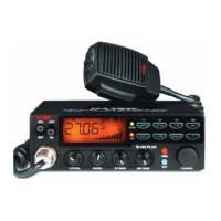
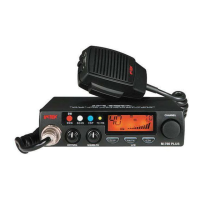
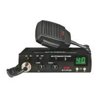
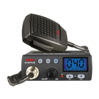
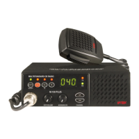
M-490 Plus
Rev,Date:
D. Phase detector and VCO control
The detector is a digital phase comparator which compares the phase of the reference signal with
programmable divider output square waves and develops a series of pulses whose DC level depends
on the phase error of each signal.
E. Transmitter/Receiver buffer AMP
Output signal of Q408 is fed into buffer AMP Q411,
F. Transmitter doubler
The output signals of Q411 goes to an amplifier with tuning circuit Q301,L301,L302 which doubles
incoming 13 MHz signals.
G. Switching of tuning capacitor in VCO
The VCO circuit must tune with a wide rang of frequencies 13.4825 ~ 13.7025 MHz (EU), 13.800625 ~
13.995625 MHz (UK) for transmitter and 16.270~16.710 MHz (EU), 16.90625 ~ 17.29625 MHz (UK) for
receiver. To comply above rang of VCO, the tuning capacitance should switched for transmission or
reception.
H. Receiver local oscillator outputs
First Mixer:
The secondary output signals is injected to the sources of 1
st
mixer Q105,Q106 in the 1
st
IF mixer
section
Second Mixer:
The output of 10.24 MHz oscillator circuit with X-1 is injected into the IF IC internally. Incoming IF
signal and 10.24 MHz are mixed inside the IF IC to extract 2
nd
IF signal 455 KHz. FM,AM audio
signals are recovered with the way of quadrature detector, AM signals are recovered with envelope
detector.
Created by: Approved by: Rev.No:
For Stage: Release Date: Page: 23 / 61