I/O
INTERFACING
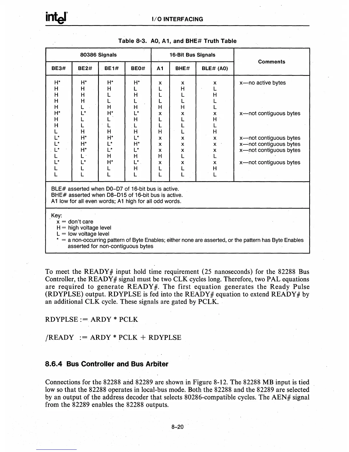
Table
8-3.
AO,
A1, and BHE#
Truth
Table
80386 Signals
16·Bit Bus Signals
Comments
BE3# BE2# BE1#
BEO#
A1
BHE#
BLE#
(AO)
H*
H* H* H*
x x x
x-no
active bytes
H
H H L
L H
L
H H L H L L H
H H L L L L L
H L H H H H L
H*
L*
H*
L*
x x x
x~not
contiguous bytes
H L L
H
L L H
H L L L L L L
L
H H H H L H
L*
H*
H*
L*
x x x
x-not
contiguous bytes
L*
H*
L*
H*
x
x x
x~not
contiguous bytes
L*
H*
L* L*
x x
x
x-not
contiguous bytes
L
L'
H H H L L
L*
L*
H*
L*
.
x x x
x-not
contiguous bytes
L
L
L
H L L H
L
L
L
L L L L
BLE#
asserted when
00-07
of 16-bit bus
is
active.
BHE#
asserted when
08-015
of 16-bit bus
is
active.
Allow
for
all
even words;
A1
high for
all
odd words .
.
Key:
x = don't care
H = high voltage level
L = low voltage level
• = a non-occurring pattern of Byte
Enables;
either none
are
asserted, or the pattern
has
Byte Enables
asserted for non-contiguous bytes
To meet the READY # input hold
time
requirement (25 nanoseconds) for
the
82288 Bus
Controller,
theREADY#
signal must be two CLK cycles long. Therefore, two PAL equations
are
required
to
generate
READY
#.
The
first
equation
generates
the
Ready
Pulse
(RDYPLSE) output. RDYPLSE
is
fed into the READY # equation to extend READY # by
an additional
CLK
cycle. These signals are gated by PCLK.
RDYPLSE : = ARDY *
PCLK
/READY
: = ARDY * PCLK + RDYPLSE
8.6.4 Bus Controller and Bus Arbiter
Connections for the 82288 and 82289 are shown in Figure 8-12. The 82288 MB input
is
tied
low so
that
the 82288 operates in local-bus mode. Both the 82288 and the 82289 are selected
by an output of the address decoder
that
selects 80286-compatible cycles. The
AEN#
signal
from the 82289 enables the 82288 outputs.
8-20
.

 Loading...

