o 0 0 0
F F F 0
FFFO
90
FFFl
90
FFF2
EB
FC
F F F 4
PHYSICAL DESIGN AND DEBUGGING
ASSUME
CS:SIMPLEST_CODE
SIMPLEST
CODE
SEGMENT
ORG
OFFFOH
START:
NOP
NO
P
JMP
START
SIMPLEST
CODE
ENDS
END
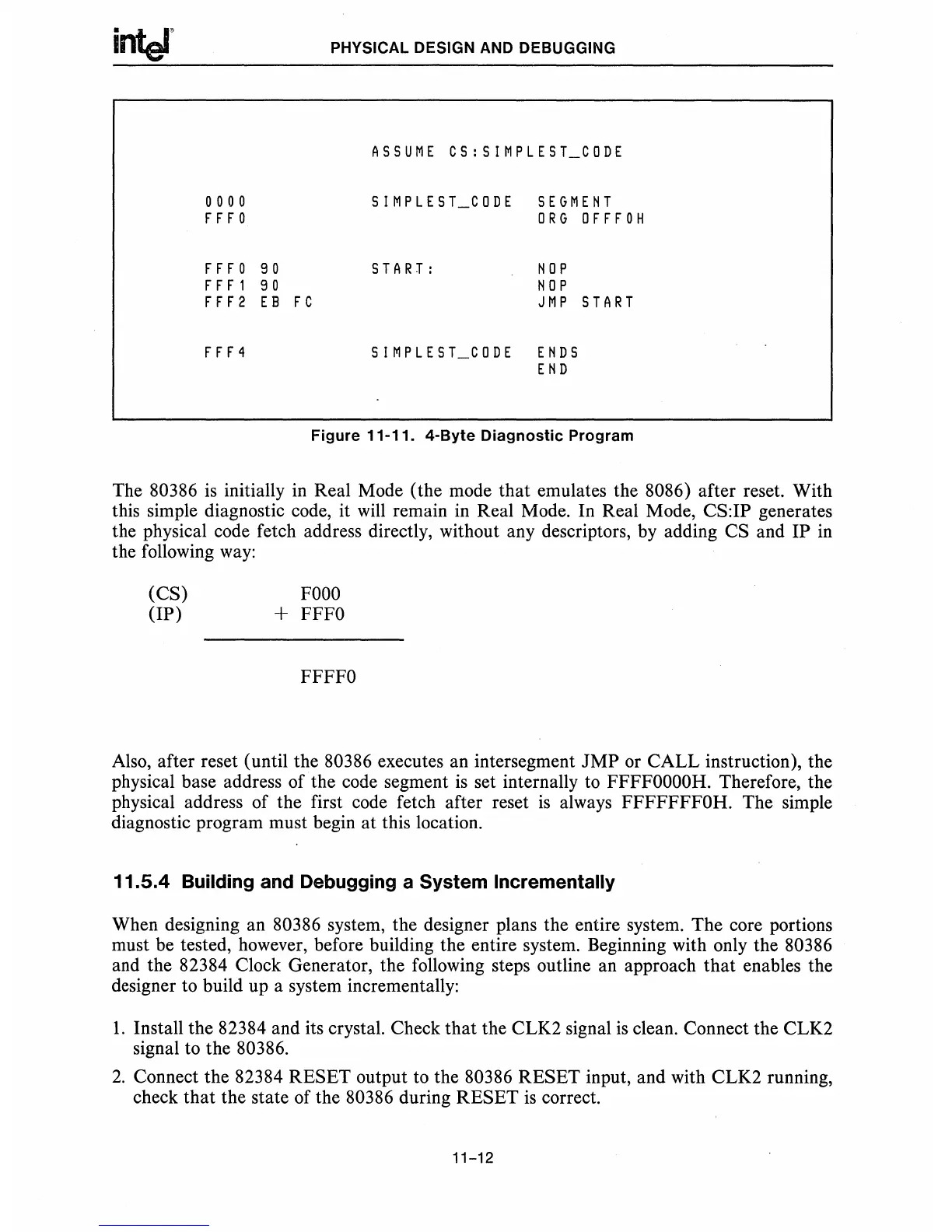
Figure
11-11.
4-Byte
Diagnostic
Program
The 80386
is
initially
in
Real Mode (the mode that emulates the 8086) after reset. With
this simple diagnostic code, it
will
remain in Real Mode. In Real Mode, CS:IP generates
the physical code fetch address directly, without any descriptors, by adding CS and IP
in
the following
way:
(CS)
(IP)
FOOO
+
FFFO
FFFFO
Also, after reset (until the 80386 executes an intersegment
JMP
or CALL instruction), the
physical base address of the code segment
is
set internally to
FFFFOOOOH.
Therefore, the
physical address of the first code fetch after reset
is
always FFFFFFFOH. The simple
diagnostic program must begin at this location.
11.5.4 Building and Debugging a System Incrementally
When designing an 80386 system, the designer plans the entire system. The core portions
must be tested, however, before building the entire system. Beginning with only the 80386
and the 82384 Clock Generator, the following steps outline an approach
that
enables the
designer to build up a system incrementally:
1.
Install the 82384 and its crystal. Check that the CLK2 signal
is
clean. Connect the CLK2
signal to the 80386.
2.
Connect the 82384 RESET output to the 80386 RESET input, and with CLK2 running,
check that the state of the 80386 during RESET
is
correct.
11-12
 Loading...


