LOCAL BUS INTERFACE
The requesting bus master must maintain HOLD active until it
no
longer needs the bus.
When HOLD goes
low,
the 80386 drives HLDA
low
and begins a bus cycle (if one
is
pending).
For valid system operation, the requesting bus master must not take control of the bus before
it receives the HLDA signal and must remove itself from the bus before de-asserting the
HOLD signal. Setup and hold times relative to
CLIO
for both rising and falling transitions
of the HOLD signal must be met.
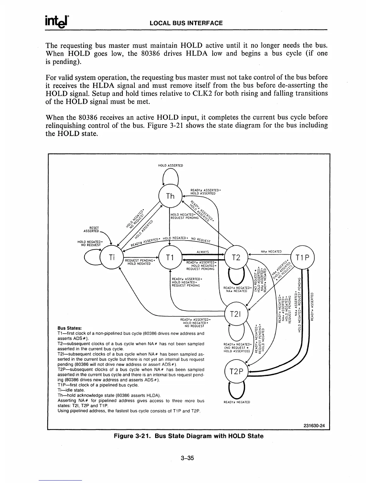
When the 80386 receives an active HOLD input, it completes the current bus cycle before
relinquishing control of the bus. Figure
3-21
shows the state diagram for the bus including
the HOLD state.
Bus Slales:
RESET
ASSERTED
HOLD
ASSERTED
READY/I
ASSERTED-
HOLD
NEGA
T£O·
NO
REQUEST
T1-first
clock of a non-pipeltned
bus
cycle (80386 drives new address
aod
asserts ADS
#).
T2-subsequent
clocks of a bus cycle when NA # has not been sampled
asserted in the current bus cycle.
T21-subsequent clocks of a bus cycle when
NA
# has been sampled
as-
serted
in
the current bus cycle but there
is
not yet
an
internal bus request
pending (80386
will not drive new address or assert ADS
#)
T2P-subsequent
clocks of a bus cycle when NA # has been sampled
asserted in the current bus cycle and there
is
an
internal bus request pend-
ing
(80386 drives new address and asserts ADS
#).
T1
P-first
clock
of
a pipe lined bus cycle.
Ti-idle
state.
Th-hold
acknowledge state (80386 asserts HLDA).
Asserting NA
# for pipelined address gives access to three more bus
states:
T21.
T2P and
T1
P.
Using pipelined address, the fastest bus cycle consists of
T1
P and T2P.
REAOY#
NEGATED
Figure
3-21.
Bus
State
Diagram
with
HOLD
State
3-35
231630·24

 Loading...

