LOCAL
BUS
INTERFACE
3.7
RESET
RESET starts or restarts the 80386. When the 80386 detects a low-to-high transition on
RESET, it terminates all activities. When RESET
goes
low
again, the 80386
is
initialized
to a known internal state and begins fetching instructions from the reset address.
3.7.1
RESET
Timing
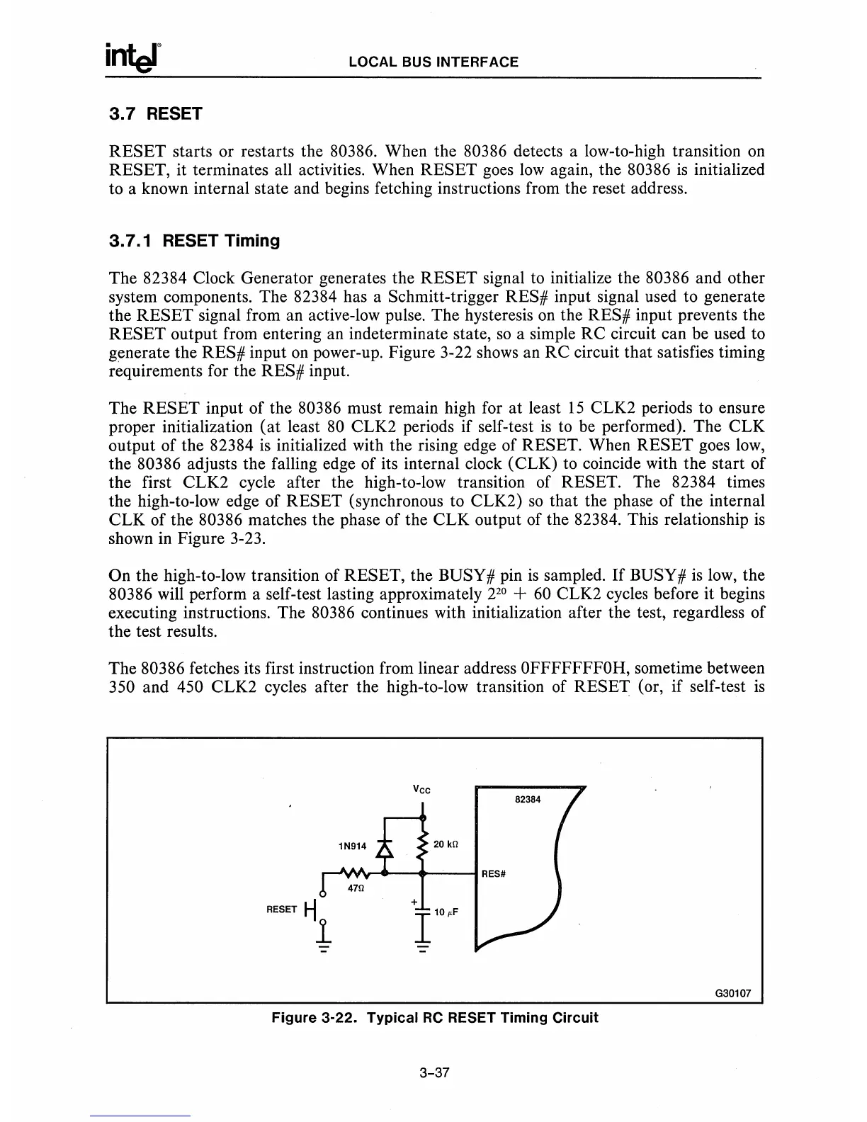
The 82384 Clock Generator generates the
RESET signal
to
initialize the 80386 and other
system components. The 82384 has a Schmitt-trigger
RES# input signal used to generate
the
RESET signal from an active-low pulse. The hysteresis
on
the RES# input prevents the
RESET output from entering an indeterminate state,
so
a simple RC circuit can be used to
generate the
RES# input
on
power-up. Figure 3-22 shows an RC circuit that satisfies timing
requirements for the
RES# input.
The
RESET input of the 80386 must remain high for
at
least
15
CLK2 periods to ensure
proper initialization
(at
least
80
CLK2 periods if self-test
is
to be performed). The CLK
output of the 82384
is
initialized with the rising edge of RESET. When RESET goes
low,
the 80386 adjusts the falling edge of its internal clock (CLK) to coincide with the start of
the first CLK2 cycle after the high-to-low transition of
RESET. The 82384 times
the high-to-low edge of
RESET (synchronous to CLK2)
so
that the phase of the internal
CLK of the
80386 matches the phase of the CLK output of the 82384. This relationship
is
shown in Figure 3-23.
On the high-to-low transition of RESET, the BUSY # pin
is
sampled.
If
BUSY #
is
low,
the
80386 will perform a self-test lasting approximately 2
20
+
60
CLK2 cycles before it begins
executing instructions. The
80386 continues with initialization after the test, regardless of
the test results.
The
80386 fetches its first instruction from linear address OFFFFFFFOH, sometime between
350 and 450 CLK2 cycles after the high-to-low transition of RESET (or, if self-test
is
RESET
.-j
1
Vee
20
kG
+
110~F
Figure 3-22. Typical
RC
RESET Timing Circuit
3-37
G30107