inter
lOCAL
BUS
INTERFACE
I
4>1
I
4>2
I
4>1
I
4>2
I
4>1
I
4>2
I
4>1
I
4>2
I
CLK2
[
RES#
[\"""-----------55
5
RESET
[
_____
.Jr"--~------:S
5---
82384
ENSURES
THAT
ITS
RESET
OUTPUT
FALLING
EDGE
OCCURS
DURING
PHASE
TWO
{\------
80386
ASSUMES
RESET
FALLING
EDGE
OCCURS
DURING
PHASE
TWO,
AND
SETS
ITS
OWN
INTERNAL
PHASE
TO
MATCH
231659-7
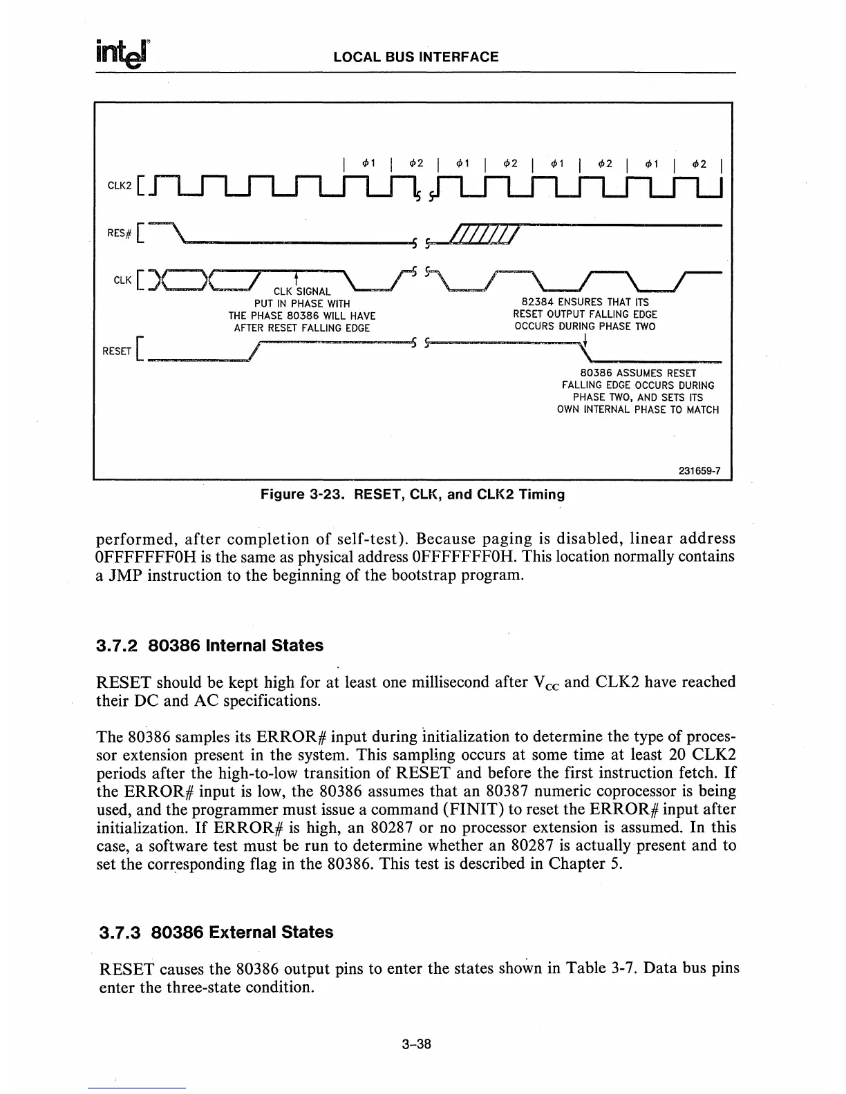
Figure 3-23_ RESET, ClK, and
ClK2
Timing
performed,
after
completion
of
self-test)_ Because paging is disabled, linear address
OFFFFFFFOH
is
the same
as
physical address OFFFFFFFOH. This location normally contains
a
JMP
instruction to the beginning of the bootstrap program.
3.7.2
80386
Internal States
RESET should be kept high for at least one millisecond after V
cc
and CLK2 have reached
their DC and AC specifications_
The 80386 samples its
ERROR#
input during Initialization to determine the type of proces-
sor extension present in the
system_
This sampling occurs
at
some time at least
20
CLK2
periods after the high-to-low transition of RESET and before the first instruction fetch.
If
the
ERROR#
input
is
low,
the 80386 assumes that an 80387 numeric coprocessor
is
being
used, and the programmer must issue a command
(FINIT)
to reset the ERROR# input after
initialization_
If
ERROR#
is
high, an 80287 or
no
processor extension
is
assumed_
In this
case, a software test must be run to determine whether an 80287
is
actually present and to
set the corresponding flag
in
the
80386_
This test
is
described
in
Chapter
5.
3.7.3
80386
External States
RESET causes the 80386 output pins to enter the states shown in Table
3-7.
Data bus pins
enter the three-state condition_
3-38