Intel Desktop Board D2500HN Product Guide
32
Connecting to the Serial Header
Figure 9, C shows the location of the serial header. Table 8 shows the pin
assignments and signal names for the serial header.
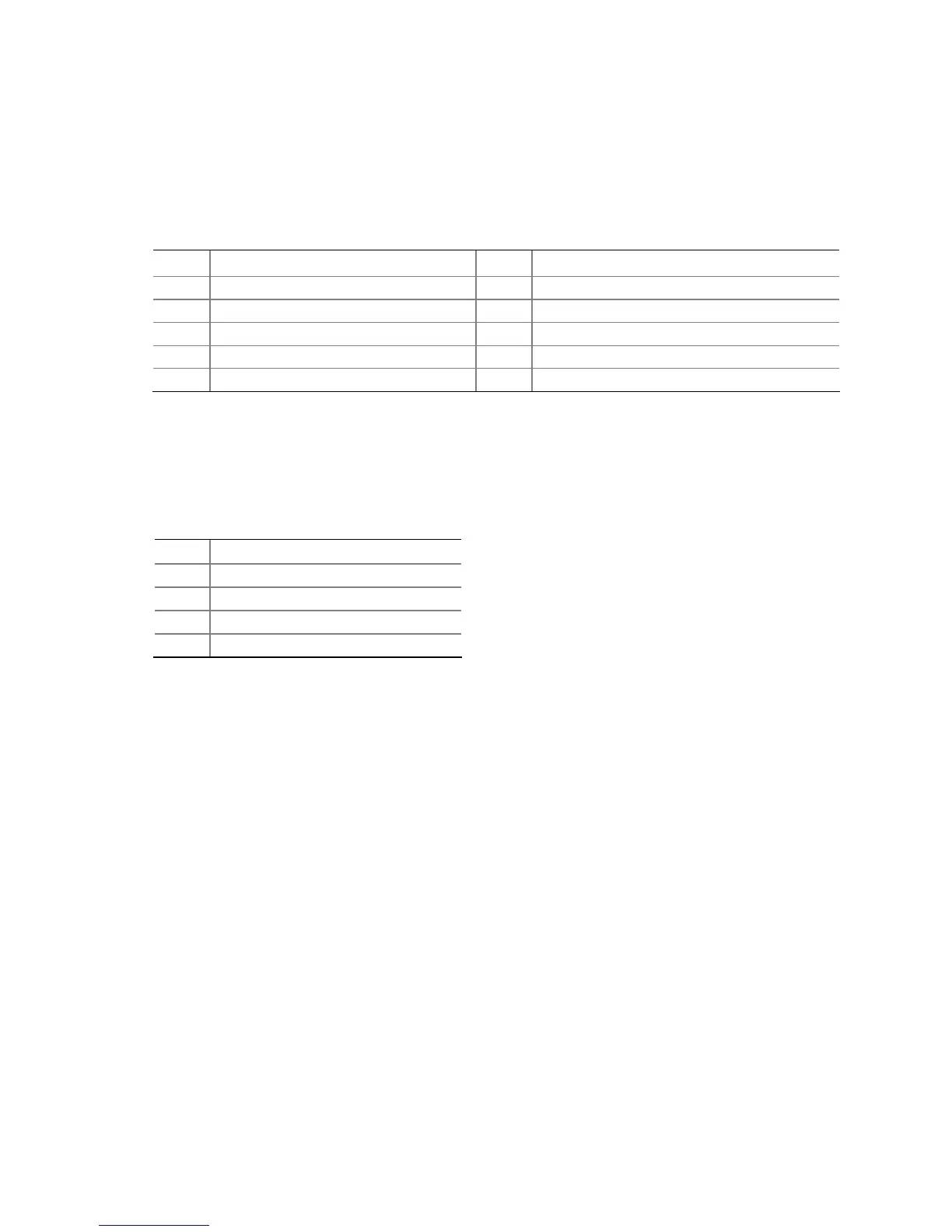
Table 8. Serial Port Header
Pin Signal Name Pin Signal Name
1 DCD (Data Carrier Detect) 2 RXD# (Receive Data)
3 TXD# (Transmit Data) 4 DTR (Data Terminal Ready)
5 Ground 6 DSR (Data Set Ready)
7 RTS (Request To Send) 8 CTS (Clear To Send)
9 RI (Ring Indicator) 10 Key (no pin)
Connecting to the Piezoelectric Speaker Header
Figure 9, D shows the location of the piezoelectric speaker header. Table 9 shows the
pin assignments for the piezoelectric speaker header.
Table 9. Piezoelectric Speaker Header
Pin Signal Name
1 + 5 VDC
2 Key (no pin)
3 Key (no pin)
4 SPKR