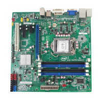
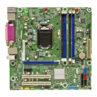
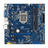
Intel Desktop Board DB65AL Technical Product Specification
14
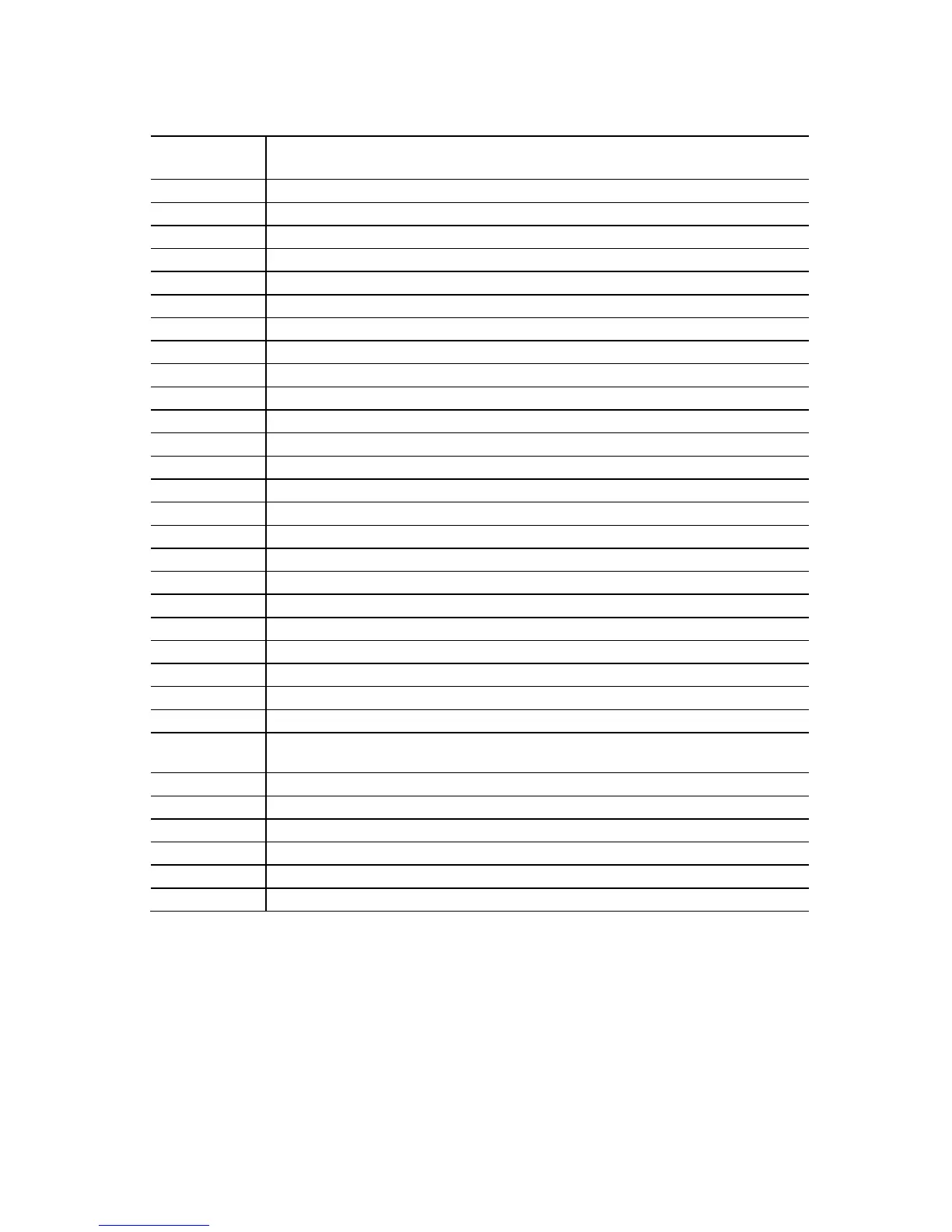
Table 2. Components Shown in Figure 1
Item/callout
from Figure 1
Descript
ion
A Conventional PCI bus add-in card connector
B Front panel audio header
C PCI Express x4 add-in card connector
D Internal mono speaker header
E PCI Express x1 add-in card connector
F PCI Express x16 add-in card connector
G Back panel connectors
H 12 V internal power connector (ATX12V)
I LGA1155 processor socket
J Processor fan header
K DIMM 3 (Channel A DIMM 0)
L DIMM 1 (Channel A DIMM 1)
M DIMM 4 (Channel B DIMM 0)
N DIMM 2 (Channel B DIMM 1)
O Serial port header
P Battery
Q Chassis intrusion header
R Front chassis fan header
S Main power connector (2 x 12)
T Standby power LED
U Piezoelectric speaker
V Intel B65 Express Chipset
W Alternate front panel power LED header
X Front panel header
Y SATA connectors (one 6 Gb/s SATA port (blue), three 3 Gb/s SATA ports (black),
and two 3 Gb/s eSATA ports (red))
Z Intel
®
Management Engine BIOS Extension (Intel
®
MEBX) Reset header
AA BIOS setup configuration jumper block
BB Intel Fast Call for Help (Intel FCFH) header
CC Front panel USB headers (4)
DD S/PDIF header
EE Rear chassis fan header