Contents
ix
4 Error Messages and Beep Codes
4.1 Speaker ......................................................................................... 73
4.2 BIOS Beep Codes ............................................................................ 73
4.3 Front-panel Power LED Blink Codes.................................................... 74
4.4 BIOS Error Messages ....................................................................... 74
4.5 Port 80h POST Codes ....................................................................... 75
5 Regulatory Compliance and Battery Disposal Information
5.1 Regulatory Compliance..................................................................... 81
5.1.1 Safety Standards.................................................................. 81
5.1.2 European Union Declaration of Conformity Statement................ 82
5.1.3 Product Ecology Statements................................................... 83
5.1.4 EMC Regulations .................................................................. 85
5.1.5 ENERGY STAR* 5.0, e-Standby, and ErP Compliance ................. 88
5.1.6 Regulatory Compliance Marks (Board Level) ............................. 282H89
93H5.2 Battery Disposal Information............................................................. 283H90
Figures
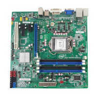
94H1. Major Board Components.................................................................. 284H13
95H2. Block Diagram ................................................................................ 285H15
96H3. Memory Channel and DIMM Configuration ........................................... 286H19
97H4. Back Panel Audio Connector Options .................................................. 287H24
98H5. LAN Connector LED Locations............................................................ 288H26
99H6. Thermal Sensors and Fan Headers ..................................................... 289H28
100H7. Location of the Standby Power LED (Green) ........................................ 290H39
101H8. Detailed System Memory Address Map ............................................... 291H42
102H9. Back Panel Connectors ..................................................................... 292H44
103H10. Component-side Connectors and Headers ........................................... 293H45
104H11. Connection Diagram for Front Panel Header ........................................ 294H51
105H12. Connection Diagram for Front Panel USB Headers ................................ 295H53
106H13. Location of the Jumper Block............................................................. 296H54
107H14. Intel MEBX Reset Header.................................................................. 297H56
108H15. Board Dimensions ........................................................................... 298H57
109H16. Localized High Temperature Zones..................................................... 299H61
Tables
110H1. Feature Summary............................................................................ 300H11
111H2. Components Shown in Figure 1 ......................................................... 301H14
112H3. Supported Memory Configurations ..................................................... 302H18
113H4. LAN Connector LED States ................................................................ 303H26
114H5. Effects of Pressing the Power Switch .................................................. 304H33
115H6. Power States and Targeted System Power........................................... 305H34
116H7. Wake-up Devices and Events ............................................................ 306H35
117H8. System Memory Map ....................................................................... 307H43
118H9. Component-side Connectors and Headers Shown in Figure 10................ 308H46