Intel Desktop Board DH55HC Technical Product Specification
12
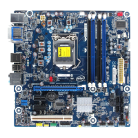
Table 2. Components Shown in Figure 1
Item/callout
from Figure 1
Descript
ion
A Conventional PCI bus add-in card connector
B Conventional PCI bus add-in card connector
C Conventional PCI bus add-in card connector
D PCI Express x1 add-in card connector
E Battery
F PCI Express x1 add-in card connector
G PCI Express x16 add-in card connector
H Back Panel Connectors
I 12 V internal power connector (ATX12V)
J Rear chassis fan header
K LGA1156 processor socket
L Processor fan header
M DIMM Channel A sockets (2)
N DIMM Channel B sockets (2)
O Front chassis fan header
P Main power connector (2 x 12)
Q Chassis intrusion header
R Intel
®
Remote PC Assist header
S SATA connectors
T BIOS setup configuration jumper block
U Alternate front panel power LED header
V Front panel header
W Standby power LED
X Front panel USB headers (2)
Y Front panel USB header with support for an Intel Z-U130 USB Solid-State Drive (or
compatible device)
Z Parallel port header
AA Intel H55 Express Chipset
BB Piezoelectric speaker
CC Serial port header
DD S/PDIF header
EE Front panel audio header
FF Internal mono speaker header