Intel Desktop Board DH55HC Technical Product Specification
44
Table 22. Intel Remote PC Assist Technology Header
Pin Signal Name
1 RPAT#
2 Ground
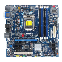
2.2.2.2 Add-in Card Connectors
The board has the following add-in card connectors:
• One PCI Express 2.0 x16: this connector supports simultaneous transfer speeds of
up to 8 GB/s of peak bandwidth per direction.
• Two PCI Express 2.0 x1: each of these connectors support simultaneous transfer
speeds of up to 500 MB/s of peak bandwidth per direction.
• Three Conventional PCI (rev 2.3 compliant) connectors.
Note the following considerations for the Conventional PCI bus connectors:
• The Conventional PCI bus connectors are bus master capable.
• SMBus signals are routed to the Conventional PCI bus connectors. This enables
Conventional PCI bus add-in boards with SMBus support to access sensor data on
the desktop board. The specific SMBus signals are as follows:
⎯ The SMBus clock line is connected to pin A40.
⎯ The SMBus data line is connected to pin A41.
2.2.2.3 Power Supply Connectors
The board has the following power supply connectors:
• Main power – a 2 x 12 connector. This connector is compatible with 2 x 10
connectors previously used on Intel Desktop boards. The board supports the use
of ATX12V power supplies with either 2 x 10 or 2 x 12 main power cables. When
using a power supply with a 2 x 10 main power cable, pins 11, 12, 23, and
24 must remain unconnected.
• Processor core power – a 2 x 2 connector. This connector provides power
directly to the processor voltage regulator and must always be used. Failure to do
so will prevent the board from booting.
CAUTION
If a high power (75 W or greater) add-in card is installed in the PCI Express x16
connector, that card must also be connected directly to the power supply. Failure to
do so may cause damage to the board and the add-in card.
Table 23. Processor Core Power Connector
Pin Signal Name Pin Signal Name
1 Ground 2 Ground
3 +12 V 4 +12 V