Technical Reference
53
2.2.2.4.3 Power/Sleep LED Header
Pins 2 and 4 can be connected to a one- or two-color LED. Table 28 shows the
possible states for a one-color LED. Table 29 shows the possible states for a two-color
LED.
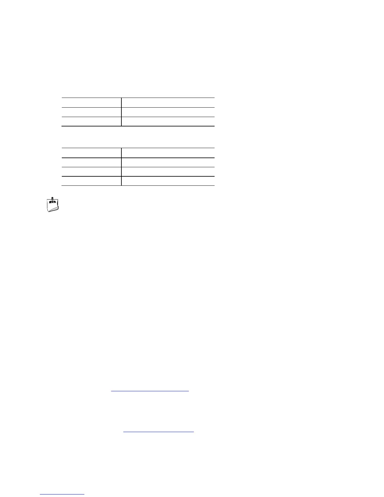
Table 28. States for a One-Color Power LED
LED State Description
Off Power off/sleeping
Steady Green Running
Table 29. States for a Two-Color Power LED
LED State Description
Steady Green Running
Steady Yellow Sleeping
NOTE
The colors listed in Table 28 and Table 29 are suggested colors only. Actual LED colors
are chassis-specific.
2.2.2.4.4 Power Switch Header
Pins 6 and 8 can be connected to a front panel momentary-contact power switch. The
switch must pull the SW_ON# pin to ground for at least 50 ms to signal the power
supply to switch on or off. (The time requirement is due to internal debounce circuitry
on the board.) At least two seconds must pass before the power supply will recognize
another on/off signal.
2.2.2.5 System ID / Custom Solutions Header
The System ID / Customs Solution header is provided for future support of All-In-One
chassis detection and to aid customers in developing custom applications.
• Prog_LED#: general purpose signal output that indicates when an event was
triggered by the operating system. Signal is amplified by a transistor. Intel can
provide sample code for customers who may want to write their own applications
leveraging this signal.
• SMB_CLK and SMB_DATA: SMBus interface, reserved for future support of All-In-
One chassis detection. General SMBus information can be found on the platform
EDS and at http://smbus.org/specs/.
• 3.3 V Standby: can be used to monitor the presence of 3.3 V standby power.
• PWRBT#: power button signal (functions in the same manner as the power button
pin on the front panel header).
• HDMI Consumer Electronics Control (CEC): standard communication signal from the
HDMI connector (http://www.hdmi.org/) - the signal is exposed through this header