Intel Desktop Board DH67GD and Intel Desktop Board DH67BL Technical Product
Specification
58
2.5.2 Fan Header Current Capability
CAUTION
The processor fan must be connected to the processor fan header, not to a chassis fan
header. Connecting the processor fan to a chassis fan header may result in onboard
component damage that will halt fan operation.
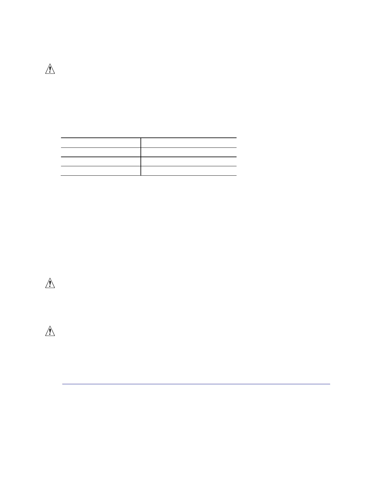
Table 35 lists the current capability of the fan headers.
Table 35. Fan Header Current Capability
Fan Header Maximum Available Current
Processor fan 2.0 A
Front chassis fan 1.5 A
Rear chassis fan 1.5 A
2.5.3 Add-in Board Considerations
The board is designed to provide 2 A (average) of current for each add-in board from
the +5 V rail. The total +5 V current draw for add-in boards for a fully loaded board
(all three expansion slots filled) must not exceed the system’s power supply +5 V
maximum current or 14 A in total.
2.6 Thermal Considerations
CAUTION
A chassis with a maximum internal ambient temperature of 38
o
C at the processor fan
inlet is a requirement. Use a processor heat sink that provides omni-directional
airflow to maintain required airflow across the processor voltage regulator area.
CAUTION
Failure to ensure appropriate airflow may result in reduced performance of both the
processor and/or voltage regulator or, in some instances, damage to the board. For a
list of chassis that have been tested with Intel desktop boards please refer to the
following website:
http://www3.intel.com/cd/channel/reseller/asmo-na/eng/tech_reference/53211.htm
All responsibility for determining the adequacy of any thermal or system design
remains solely with the reader. Intel makes no warranties or representations that
merely following the instructions presented in this document will result in a system
with adequate thermal performance.