Installing and Replacing Desktop Board Components
47
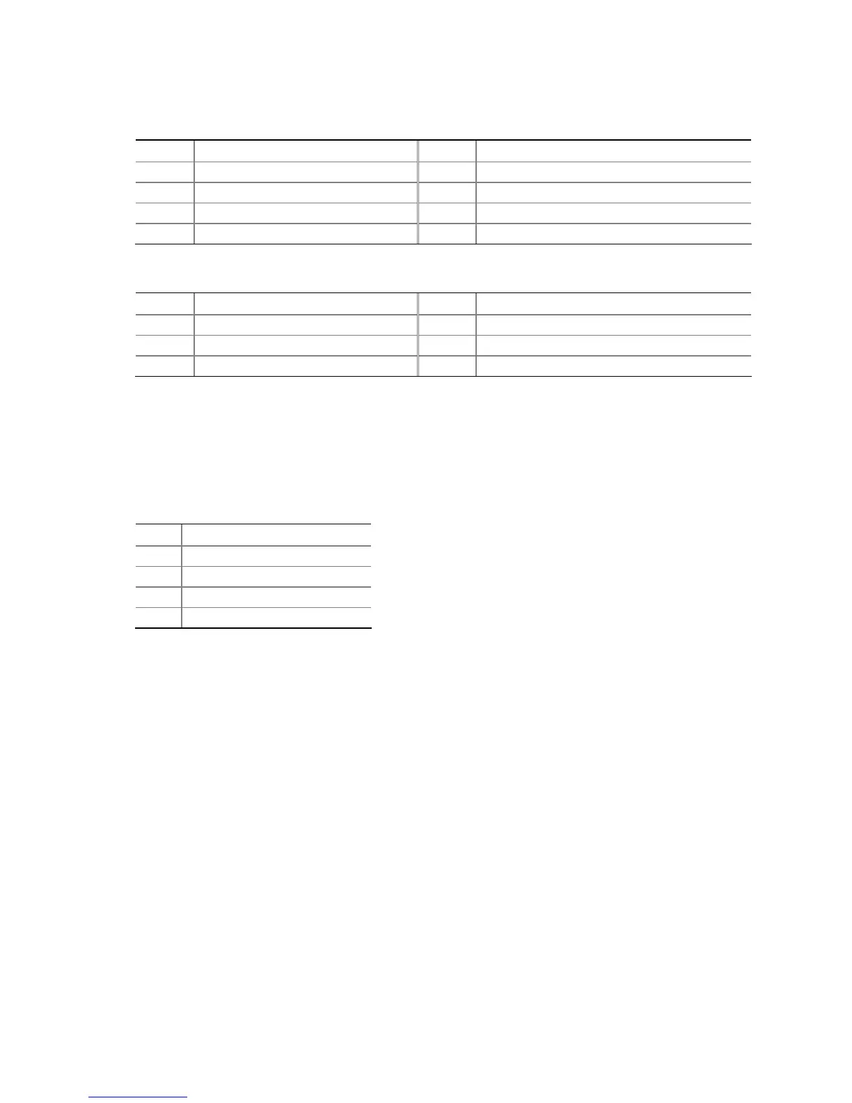
Table 11. Front Panel CIR Receiver (Input) Header Signal Names
Pin Signal Name Pin Signal Name
1 Ground 2 LED
3 No Connection 4 Learn-In
5 +5 V Standby 6 Vcc
7 Key (no pin) 8 CIR Input
Table 12. Back Panel CIR Emitter (Output) Header Signal Names
Pin Signal Name Pin Signal Name
1 Emitter Out 1 2 Emitter Out 2
3 Ground 4 Key (no pin)
5 Jack Detect 1 6 Jack Detect 2
S/PDIF Header
Figure 18, G shows the location of the S/PDIF output header. Table 13 shows the pin
assignments and signal names for the S/PDIF output header.
Table 13. S/PDIF Header Signal Names
Pin Description
1 Ground
2 S/PDIF Out
3 Key (no pin)
4 +5 VDC