Intel Desktop Board DX79SR Technical Product Specification
14
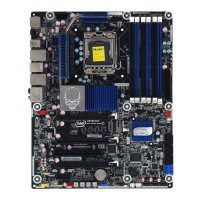
Table 2. Components Shown in Figure 1
Label Description
A Front panel audio header
B PCI Express x1 add-in card connector
C S/PDIF out header
D PCI Express 3.0 x16 add-in card connector (x8 electrical)
E Piezoelectric speaker
F Conventional PCI add-in card connector
G PCI Express 3.0 x16 add-in card connector
H PCI Express x1 add-in card connector
I PCI Express 3.0 x16 add-in card connector
J Rear chassis fan header
K Battery
L Back panel connectors
M Processor fan header
N DIMM 1 (Channel A, DIMM 0)
O DIMM 5 (Channel A, DIMM 1)
P DIMM 2 (Channel B, DIMM 0)
Q DIMM 6 (Channel B, DIMM 1)
R LGA 2011 processor socket
S 12 V processor core voltage connector (2 x 4 pin)
T DIMM 8 (Channel D, DIMM 1)
U DIMM 4 (Channel D, DIMM 0)
V DIMM 7 (Channel C, DIMM 1)
W DIMM 3 (Channel C, DIMM 0)
X Main power connector (2 x 12 pin)
Y Remote thermal probe header
Z Front chassis fan header
AA SATA 6.0 Gb/s connectors through the PCH (blue)
BB SATA 3.0 Gb/s connectors through the PCH (black)
CC SATA 6.0 Gb/s connectors through a Marvell 88SE9128 controller (gray)
DD Intel X79 Express Chipset
EE Front panel USB 2.0 headers (4)
FF Consumer IR emitter (output) header
GG BIOS Setup configuration jumper block
HH Power Fault LED
II Front panel USB 3.0 connector
JJ Alternate front panel power LED header
KK Consumer IR receiver (input) header
LL Voltage measurement test points
MM Front panel header
NN Post Code LED display
OO Front panel IEEE 1394a header
PP Onboard Reset button
QQ Onboard Power button
RR Chassis intrusion header
SS Auxiliary fan header
TT Board Status LEDs