Technical Reference
49
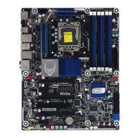
Table 11. Component-side Connectors and Headers Shown in Figure 13
Item/callout
from Figure 13
Des
cription
A Front panel audio header
B PCI Express x1 add-in card connector
C S/PDIF out header
D PCI Express 3.0 x16 add-in card connector (x8 electrical)
E Conventional PCI add-in card connector
F PCI Express 3.0 x16 add-in card connector
G PCI Express x1 add-in card connector
H PCI Express 3.0 x16 add-in card connector
I Rear chassis fan header
J Processor fan header
K 12 V processor core voltage connector (2 x 4 pin)
L Main power connector (2 x 12 pin)
M Remote thermal probe header
N Rear chassis fan header
O SATA 6.0 Gb/s connectors through the PCH (blue)
P SATA 3.0 Gb/s connectors through the PCH (black)
Q SATA 6.0 Gb/s connectors through a Marvell 88SE9128 controller (gray)
R Front panel USB 2.0 header
S Front panel USB 2.0 header
T Front panel USB 2.0 header
U Front panel USB 2.0 header
V Consumer IR emitter (output) header
W Front panel USB 3.0 connector
X Consumer IR receiver (input) header
Y Alternate front panel power LED header
Z Front panel header
AA Front panel IEEE 1394 a header
BB Chassis intrusion header
CC Auxiliary fan header