EasyManuals Logo
Home>Intel>Motherboard>Galileo

Intel Galileo Hardware Guide

Intel Galileo
34 pages
To Next Page IconTo Next Page
To Previous Page IconTo Previous Page
Page #10 background imageLoading...
Page #10 background image
Hardware 10
Hardware
2.1: External Outputs
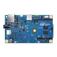
When using a Galileo, the chip itself doesn’t have a lot ways to interact with the outside world. In order to
make your Galileo do some more interesting things, you have to be able to connect external outputs.
External means it is separate from the microcontroller. The opposite word is internal. In the previous
lesson, you made the ‘internal’ LED (on the physical Galileo board) blink.
Output is something that the microcontroller can tell to do something. You can see an output light up,
move, or do something else. Outputs include motors, LEDs, and light bulbs. It is the opposite of an input,
which tells the microcontroller information based upon something in the outside world.
2.2: Connecting an LED
We have made an onboard (internal) LED light on and o on our Galileo, but now we have to start going ‘o
the board’. This means we have to provide a path from the microcontroller to the external LED and back. If we
were going to move cars back and forth, we would build a road. If we were moving water, we would make a
pipe. We are moving electricity so we need a path made of metal, which electricity can travel across. Metal
is a great conductor like you learned in Circuitry Lessons.
An easy way to connect electronic components is to use rubber-coated electrical wire. The
rubber prevents electricity going in a way we don’t expect. And the metal wire conducts
electricity across it.
To connect things we rst have to take a piece of wire, however long makes sense to you, and remove the
rubber from the ends of both sides. Take o enough to work with easily. This is called “stripping the wire”.
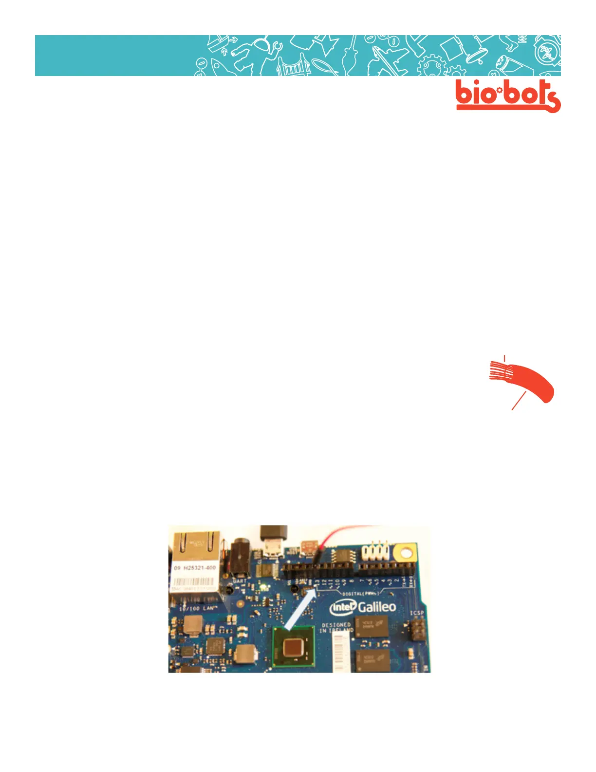
We are going to use the Blink program again (If you lost it or don’t have it, open le->examples->01. Basic-
>Blink). This program communicates through pin 13. That means we have to insert our wire into pin 13 (Lesson
2, Figure 1).
2: Make your Galileo Blink Some More
Lesson 2 Figure 1
metalwires
rubber

Other manuals for Intel Galileo

Questions and Answers:

Question and Answer IconNeed help?

Do you have a question about the Intel Galileo and is the answer not in the manual?

Intel Galileo Specifications

General IconGeneral
Product familyIntel Galileo
Product seriesIntel Galileo board
Processor cache16 KB
Processor cores1
Processor modelIntel Quark SoC X1000
64-bit computingNo
Processor socketQuark 393pin FCPGA
Product codename-
Processor frequency400 MHz
Microcontroller modelIntel Quark
Processor lithography32 nm
Processor manufacturerIntel
Thermal Design Power (TDP)12.5 W
Memory bandwidth supported by processor (max)2.5 GB/s
Memory bus32 bit
Flash memory8 MB
Memory channelsSingle-channel
Flash memory typeNorwegian
Memory clock speed800 MHz
Internal memory typeDDR3
Number of DIMM slots0
Compatible memory cardsMicroSD (TransFlash), MicroSDHC
Maximum internal memory0.256 GB
Maximum memory card size32 GB
SRAM (Static Random Access Memory)512 KB
EEPROM (Electrically Erasable Programmable Read-Only Memory)8 KB
USB version2.0
Ethernet LANYes
USB ports quantity3
Ethernet interface typeFast Ethernet
ARK ID78919
StatusDiscontinued
Launch dateQ4'13
Package size15 x 15 mm
FSBs supportedNA
Processor includedIntel® Quark™ SoC X1000 (16K Cache, 400 MHz)
Supported memory typesDDR3-SDRAM
Power over Ethernet (PoE) voltage12 V
Export Control Classification Number (ECCN)4A994
PCI SupportPCI Express
PCI Express interface data lanesx1
Form factorArduino
Market segmentDesktop
DC input voltage5 V
Intel Small Business Advantage (SBA) version0.00
Last change63903513
Processor ID79084
Product type11
Harmonized System (HS) code8471500150
Weight and Dimensions IconWeight and Dimensions
Width- mm

Related product manuals