EasyManua.ls Logo

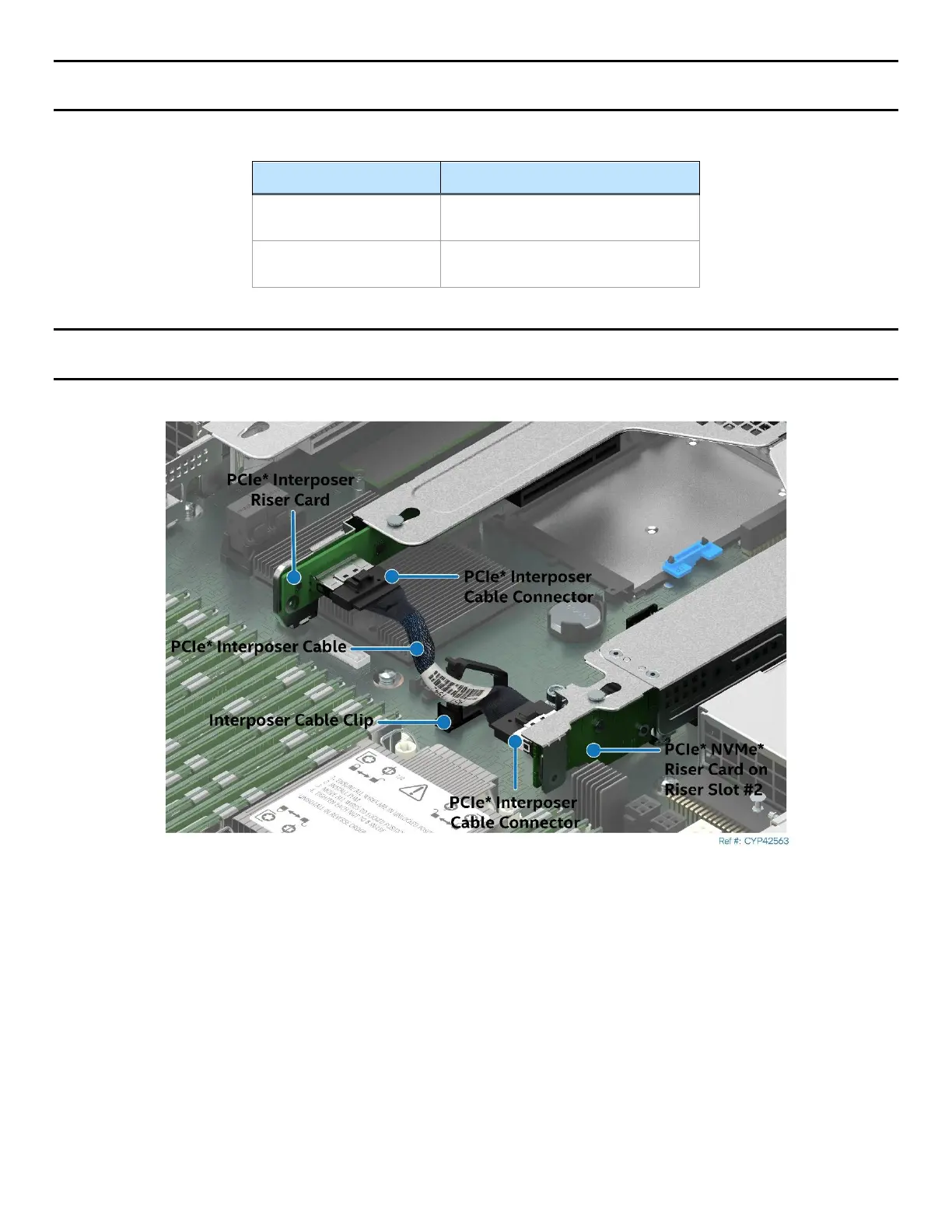
Intel M50CYP2SB Series - Figure 45. Pcie* Interposer Riser Card to Pcie* Nvme* Riser Card Connectivity; Table 32. Pcie* Nvme* Riser Card Connector Description

Intel M50CYP2SB Series
160 pages
Print Icon
To Next Page IconTo Next Page
To Previous Page IconTo Previous Page
Loading...
Intel® Server Board M50CYP2SB Family Technical Product Specification
76
Note: The PCIe_SSD_0–1 connector only supports the PCIe Interposer cable. This connector does not
support front drive bay connectivity.
Table 32. PCIe* NVMe* Riser Card Connector Description
Connector
Description
Slot1_PCIe_x16
CPU 1 – Ports 2A–2D
(x16 electrical, x16 mechanical)
PCIe_SSD_0-1
CPU 1 – Ports 1A–1B
(x8 electrical, x8 mechanical)
Note: The PCIe Interposer cable must not be completely inserted into the cable clip to ensure the cable does
not pull on the riser cards. Place the cable at the mouth of the clip as shown in the following figure.
Figure 45. PCIe* Interposer Riser Card to PCIe* NVMe* Riser Card Connectivity

Table of Contents