In the menu of P3, input [4] + [#]. The LCD will show as P24. The
right number shows current unlock time. It will change after input
a new number, then press [#] button to confirm.
[Note] Unlock time is from 1s to 9S.
(24)
Change password
In the menu of P3, input [6] + [#]. The LCD will show as P25.
Input the password, if it is correct, LCD will show as P26.
Input the new password, LCD will show as P27, then repeat to
input the password again, press [#] button to confirm. After finish,
the LCD will show as P28.
[Note] The system original password is 2003.
(25)
(27)
(26)
(28)
In the menu of P3, input [7] + [#]. The LCD will show as P29.
Input the new password, press button to confirm. After finish, the
LCD will show as P30.
[Note] The original publicpassword is 1234.
(29)
(30)
(31)
(33)
(34)
(32)
(35)
(36) (37)
In the menu of P31, input [0] + [#]. The LCD will show as P32.
Input [0]+[#], lift control function is OFF. The LCD will show as P33.
Input [1]+[#], lift control function is OFF. The LCD will show as P34.
After finish, press [*] button return to P31.
In the menu of P31, input [1]+[#]. The LCD will show as P35.
Input the floor number, press [ # ] button to confirm.
e.g. Second underground floor, input F3+[2], as the P36 shows.
1 floor, input [0]+[1] ,as the P37 shows.
In the menu of P3, input [8] + [#]. The LCD will show as P31.
■ Change resident password
In the standby state, press [F2] button, the LCD will show as P38.
Input the digit as follows prompt:
◆Room number e.g.0101
◆Current password e,g.1234
◆New password e,g.5678
◆Repeat the new password e.g.5678
If the password is correct, the door station will sound a long beep,
then return to standby state.
8
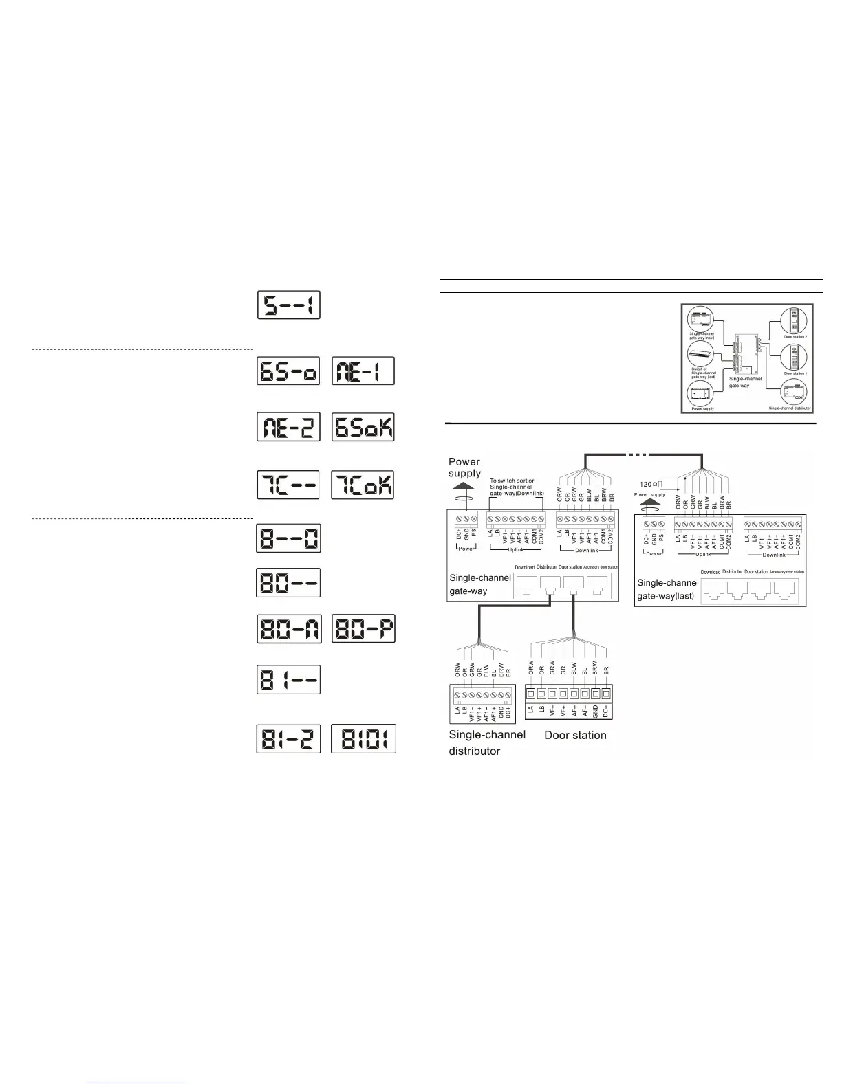
Gate-way wiring diagram
1. Accessory door station’s wiring method is the same as door station.
2. Between the [Uplink] terminals (LA, LB) on the last gate way in the n
should have 120Ω resistance, [Downlink] terminals
connected.
3. When wiring for power supply, PS ports should not be connected.
 Loading...