LENS RETAINER
Take out the existing lens, and put
the new one in with the SMOOTH
side facing outward. Install the lens
with the small slot at the top. The large
slot on the bottom of the lens should be
seated over the tab on the bottom of the front cover.
INSTALLATION INSTRUCTIONS
Securely mount the rear housing at the desired location. When mounting
the sensor on a wall, use the two keyholes in the back of the rear housing.
When mounting the sensor in a corner, use the breakout tabs on the beveled
corners of the unit. A swivel mount bracket (Model SMB-10) is also available
from IntelliSense.
Observing the proper polarity, wire the sensor as shown below (use 22
- 14 AWG). Do not leave excess wire inside the unit. Push as much of the
wire as possible back into the wall when returning the PCB to its housing.
TB1
NO C NC V- V+
ALARM
500 mA, 30 VDC
POWER
35 mA, 12 VDC
TB2
TB1
TB2
TAMPER
25 mA, 30 VDC
NC
TAMPER
25 mA, 30 VDC
NC
CNC
V- V+
ALARM
100 mA, 30 VDC
POWER
35 mA, 12 VDC
Models
DT-420T
DT-435T
DT-450T
To remove the sensor's front
cover, use a small screw-
driver to push down on the
latch at the top of the unit,
while separating the housing
parts.
To remove the printed circuit board
(PCB), lift up on the latch at the top of
the unit, while using the microwave
antenna to gently pull the PCB
forward.
CONTINUED
To change the Fresnel lens,
remove the sensor's front cover.
Next remove the lens retainer by
depressing the retainers
brackets on either side of the
lens retainer.
NOTE: Two additional lenses are available for these sensors. The pet-alley
lens blocks lower PIR zones to exclude pets from the field of view; the barrier
lens blocks outer zones for narrow applications.
When the pet-alley lens is used, install a look-down mask (provided) over the
inside of the look-down window, and make sure to mount the sensor at a
height of 4'.
The optional lenses are available at no charge from your local distributor, or
call IntelliSense at (800) 573-0154. Order Part Number 0-000-400-03.
A range thumbwheel for the microwave is located at the upper left edge
of the PCB (R53). When the PCB is oriented in the correct mounting position,
and you are facing it, turning the thumbwheel toward the bottom of the
PCB will INCREASE the range of the microwave. Refer also to the label
pasted on the microwave antenna.
Before walk-testing the sensor, set the microwave range thumbwheel at
MINIMUM by turning it toward the top of the PCB (as far as it will go). Then,
as you perform the walk-test, gradually increase the sensitivity of the
microwave until the desired range is obtained.
PIR range is determined by the mounting height and angle, or by masking
specific PIR zones.
Snap the lens retainer back into place, then re-assemble the housing.
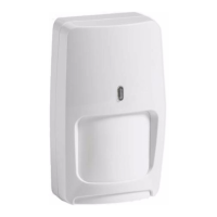
DT-400T series motion sensors combine two technologies into one small,
attractive package. Within a defined area, the microwave detector senses
motion, and the passive infrared (PIR) detector responds to radiant body
heat (infrared energy emitted by an intruder).
DT-400T sensors also feature a new TURBO circuit which provides more
protection against false alarms than ever before. The TURBO circuit allows
the microwave to "idle" until the PIR detects a change in infrared energy.
When the PIR detects a change in infrared energy, the microwave instantly
becomes "alert." If it detects motion within a specific time period, the sensor
will alarm. Because both technologies must verify intrusion at or about the
same time, false alarms are virtually eliminated.
DT-400T sensors are also among the first to have both a Fresnel lens and
multi-segmented PIR mirror. This unique optical system provides dense PIR
coverage from directly beneath the unit (look-down zones) to maximum
range.
In addition, DT-400T sensors are equipped with a supervision circuit that
constantly monitors the microwave technology. If a problem is detected,
the sensors will electronically signal an alarm to the control panel.
DT-420T 20' x 20' 6 m x 6 m
DT-435T 35' x 30' 11 m x 9 m
DT-435TC 35' x 30' 11 m x 9 m
DT-450T 50' x 40' 15 m x 12 m
DT-450TC 50' x 40' 15 m x 12 m
Model
DT-435TC
DT-450TC
MOUNTING PROCEDURE
Select the best location in the room for both technologies. Aim the sensor
toward the interior of the room, away from windows, moving machinery, and
heating/cooling sources.
Maximum range is obtained at a mounting height of 7'6" (2.3 m). Make
sure the sensor has a clear line of sight to all areas you wish to protect.
Infrared radiation cannot penetrate solid objects. If the PIR is blocked, the
unit will not alarm.
MOUNTING LOCATION
WIRING
CHANGING THE FRESNEL LENS
RANGE ADJUSTMENT
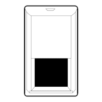
LATCH
Figure 1
DT-400T Assembly
Small
Slot
LENS
LENS RETAINER
BRACKET
Figure 2
Lens Change Assembly
Microwave/PIR technology
.
Automatic temperature
compensation
.
DT 420T, DT 435T, DT 450T
Energized Form A alarm relay
.
Energized Form C alarm relay
DT 435TC, DT 450TC
.
Enhanced run-through
detection
.
Shorter reset times
.
.
Optional barrier and pet-alley
lenses available.
New TURBO circuit
.
.
Dual element PIR
Microwave supervision
.
.
Single edge PIR triggering
Low 35 mA current draw at
12 VDC
.
9 - 14 VDC operation
.
.
Unique PIR optics
FEATURES
.
Exposed LEDs
.
All models are UL listed
.
DT-435TC and DT450TC are
also ULC listed
All the walk-test LEDs are located at the bottom, left side of the unit. DT-400T
sensors are equipped with two diagnostic LEDs: green for PIR and yellow
for microwave. The red LED is used to indicate an alarm condition.
Apply power to the sensor and let it warm up for at least three minutes. Begin
walk-testing after all three LEDs have gone out.
SYSTEM TESTING