EasyManua.ls Logo

IntelliSense DT-7225 User Manual

Default Icon
2 pages
To Next Page IconTo Next Page
Page #1 background imageLoading...
Page #1 background image
DT-7225 DUAL TEC
®
Motion Sensor Installation Instructions
TT
Step 1
Separate the sensor housings and remove
Printed Circuit Board (PCB).
Use a small screwdriver to unfasten the hous-
ing latch and separate the sensor housings.
Push outward on the PCB latch to lift the PCB
out of the housing.
Step 3
Wire the sensor.
Observing the proper polarity, wire the unit as
shown in the illustration below, use 1.02 to 0.64 mm
(18 to 22 AWG) wire.
Step 2
Mount the sensor.
Break out the mounting/wiring knockouts and
mount the sensor in an appropriate location.
An ideal location meets the following objectives:
Allows a clear line-of-sight to all areas to
protect.
Does not directly face windows.
Avoids close proximity to moving machinery,
fluorescent lights, and heating/cooling
sources.
NOTE: maximum range is obtained at a
mounting height of 2.3 m (76).
Knockout
Housing
latch
PCB latch
FRONT HOUSING
REAR HOUSING AND PCB
Terminal Block (TB1)
PCB
LED
(DS1)
LED Enable
(Cut or remove
LED enable
jumper J1 to
disable LED)
Step 4
Walk-test the sensor.
After returning the PCB to the rear housing,
reassemble the sensor housing. Apply
power to the sensor and begin walk-test
when the red LED is off.
Walk across the detection area at the ranges
to be covered. The red LED should indicate
an alarm condition after 2 to 4 normal steps.
When there is no motion in the detection
area the LED should be off.
TB2
Alarm
500 mA
30 VDC
Power
25 mA
7.5-16 VDC
(UL: 8.9-14.5 VDC)
TB1
DT-7225
Tamper
50 mA
24 VDC
TB2
Question and Answer IconNeed help?

Do you have a question about the IntelliSense DT-7225 and is the answer not in the manual?

IntelliSense DT-7225 Specifications

General IconGeneral
BrandIntelliSense
ModelDT-7225
CategoryAccessories
LanguageEnglish

Summary

Sensor Installation and Testing

Separate Sensor Housings and PCB

Unfasten housing latch, separate housings, and lift PCB from housing using the latch.

Mount the Sensor

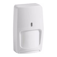
Break out knockouts, mount sensor in an ideal location for clear line-of-sight and optimal coverage.

Wire the Sensor

Wire the unit observing polarity, using 1.02 to 0.64 mm (18 to 22 AWG) wire.

Walk-test the Sensor

After reassembly, apply power and walk-test. LED should indicate alarm after 2-4 steps when motion is detected.

Sensor Specifications and Patterns

Detection Patterns

Illustrates the detection range and coverage area of the DT-7225 sensor.

Microwave Supervision

Explains sensor lock into alarm if microwave signal is lost; LED does not light.

Product Specifications

Details range, alarm relay, power requirements, frequencies, immunity, and operating temperature.

Approvals and Listings

Lists FCC, IC, and UL certifications for the DT-7225 sensor.

Related product manuals