CONTROLLED LOADS
50 AMP Smart
EMS
EMS
OPERATION IN VEHICLES USING AVAILABLE SERVICE
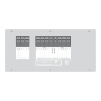
The system offers control of up to six powered loads; each one connected to one of the relay circuits of the
system. Four of these relays, relays 1, 2, 3, and 4, are 30 Amp relays with normally-open contacts used to interrupt the
120 volt power to the loads. These circuits are intended to control 120 volt appliances such as refrigerator, water heater,
washer/dryer, coffee maker, etc.
For the 120 VAC switched loads, power is routed from the individual branch circuit breakers to one of these 120 VAC relays on
the Control Module. The controlled load is then fed from that relay.
The remainder of the relays, relays 5 and 6, are intended to switch low voltage loads. Relays 5 and 6 are single-pole, double-
throw relays with all contacts available. These relays are intended to control air conditioners, or other appliances equipped
with low voltage controls or thermostats. The contacts of the relays are typically wired in series with the low voltage controls, or
thermostats of air conditioners so the turns off only the compressor, or the compressor and fan. These circuits could also
control other 120 volt appliances if an additional control relay is added externally.
TM
The is turned on by the presence of 120VAC, or 240VAC at the L1 or L2 inputs (J6, pin 3 and 1 respectively). This feature
is intended to prevent the from drawing excessive current from the +12 VDC battery supply when not in operation.
When 120 VAC or 240 VAC power is applied, the system automatically powers up and determines the nature of the power
source.
If the generator is running, a +12 VDC signal will be present at J2 pin 2 on the Control Module.
If 240 VAC exists between the L1 and L2 inputs, the energy management feature is disabled and all control relay contacts are
closed, energizing all of the controlled loads. The Control Module sends a signal to the Display Module which causes the load
meter to go blank, and all power status indicators to light. If the generator is running, the GEN SET service indicator will light,
otherwise the 50A service indicator on the Display Module will light.
If the L1 and L2 inputs are at the same voltage (0 Volts between L1 and L2 and 120 VAC between either L1 or L2 and Neutral)
the Control Module sends a signal to the Display Module causing the load meter to display actual load current and the GEN
SET service indicator to light. If the Genset EMS feature is not enabled all loads will be turned on, independent of the
load rating of the generator, and all power status indicators will light. If the Gen Set EMS featured is enabled ,
loads will turn ON until the load rating of the generator is reached and the status indicators for those loads will light.
If 120 VAC is present at the L1 and L2 inputs and +12 VDC signal is present at J2 pin 2 on the Control Module, the will
assume that 120 VAC, 30 Amp shore power is available and the energy management feature will be enabled. If only 20 Amp
service is available, the user by momentarily pressing the 20/30 Amp select switch on
the Control Panel.
Initially, the control turns all loads on with a one-second interval and the total current is monitored. If the total current should
exceed the service limit, the system will turn off the first load in the shedding table. As it turns the loads off, it calculates the
amount of current that was removed, which is the value for that load. This value is placed in memory. If the current remains
above the service limit, the system will turn off the next load in the shedding table. Again, it calculates the amount of current
that was removed and places the value for that load in memory. The system continues to turn off loads until the total current
falls below the service limit, or all of the six controlled loads have been shed. Through this process, the system has "learned"
the amount of current that each particular load draws. This feature compensates for the differences in current draw over a
range of line voltage and ambient temperature, by re-learning the load each time it is turned off, or "shed".
The now waits until the total current is lower than the service limit and enough current is available
before it will turn that load back on. This assures that there is
sufficient current to operate the load.
There is a period after a load is shed before the load can be turned back on again, to
prevent air conditioners from turning on with a head of pressure. During this delay period, if there is enough current
available to energize the load, the LED status indicator for that load will flash. After the delay period expires, the load
will be energized and the indicator will turn ON.
EMS
EMS
240 VAC 50A SERVICE
no EMS
50 Amp Smart EMS
two-minute minimum delay
120 VAC GEN-SET SERVICE
120 VAC SHORE POWER
(default)
(installers option)
(as
compared with the amount in memory for the last load shed)
must select the 20 AMP service mode
TM
NOTE:
3
131 Eisenhower Lane North
Lombard, IL 60148
630.268.0010 / 1.800.251.2408
50 AMP Smart Energy Management System Model 800
TM
P/N 53-00894-100 Rev. E 030807
www.intellitec.com
Intellitec
 Loading...