DISPLAY PANEL
Select a convenient location for the panel, where it can be easily viewed by the owner.
The Display Panel is equipped with a six inch long pigtail with a 3-pin Mate-N-Lock female connector. An extension
harness, up to 100 feet long, can be attached between the Display Panel and the EMS Control Module, with a 3-pin
male Mate-N-Lock plug at the Display Panel end and a 4-pin, male, Mate-N-Lock plug at the Control Module end.
1) Stand-Alone Mode - Pins 1 thru 3 on the 3-pin plug connect to the corresponding pins on the 4-pin plug.
In addition, pin 4 on the 4-pin plug should be connected to pin 2.
2) RV Multiplex Master Mode - Pins 1 thru 3 on the 3-pin plug connect to corresponding wires in the RV Multiplex system
and the corresponding pins on the 4-pin plug. In addition, pin 4 on the 4-pin plug should be connected to pin 2.
3) PMC Mode - Pins 1 thru 3 on the 3-pin plug connect to the corresponding pins on the 4-pin plug.
should be made to pin 4 on the 4-pin plug.
The Display Panel should be plugged onto the mating 3-pin, Mate-N-Lock connector in the harness, insuring that it is fully
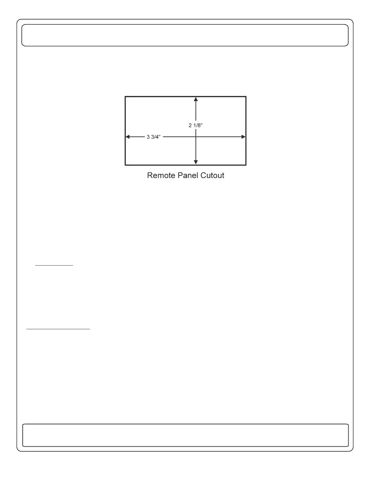
seated and locked. The panel should then be installed in the hole and screwed in place using two, # 6, flat head screws
through the holes in the panel. A white function label should be lettered to correspond to the order of load shedding and
installed behind the cover label. The cover label should be placed against the front panel and the trim bezel snapped on to
hold the label in place.
Plug the 4-pin plug into J5 on the EMS Control Module, insuring that it is fully seated and locked.
Cut a hole for the panel as shown:
,,
The wiring of the plug at the Control Module end determines the system configuration as follows:
No connection
PERFORMANCE TEST
The system is now ready for testing.
At the installers preference, to assure there are no potential shorts, a Hi-Pot test can be performed on the installation. To do
this, +12 volts must be applied to the system. A jumper wire must be installed to tie the two pins of the “Hi-Pot Test" plug, J1,
to turn the system ON without the presence of 120 volt power. This plug is located on the right side of the EMS Control
module. The relays on the module should be heard clicking as they pull in. On the Display Panel, the LED's should light
and the numeric display should read "0". The Hi-Pot test should now be conducted in accordance with standard
procedures for the tester being used. Assuming the system passes, the covers should be taken off and the jumper
removed from J1.
HI-POT TEST
If not, the problem must be corrected before proceeding further.
10
131 Eisenhower Lane North
Lombard, IL 60148
630.268.0010 / 1.800.251.2408
50 AMP Smart Energy Management System Model 800
TM
P/N 53-00894-100 Rev. E 030807
www.intellitec.com
Intellitec
 Loading...