DISTRIBUTION PANEL (continued)
Connections are as follows:
Common Normally Open
Normally Closed
Common Normally Closed In this way, the EMS can interrupt the operation of the
compressor, just as the thermostat does.
Normally Closed
Common Normally Closed In this way, the EMS can interrupt the operation of the
compressor and fans, just as the thermostat does.
Normally Closed
Common Normally Closed
Normally Closed
Common Normally Closed
In this way, the EMS can interrupt the operation of the fan, just as the thermostat does.
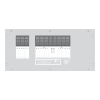
The low voltage controlled load connections are made through J4 (6 pin Mate-N-Lok connector on the low voltage side of
the control module).
1 Relay 5 N. O.
2 Relay 5 COMMON
3 Relay 5 N. C.
4 Relay 6 COMMON
5 Relay 6 N. C.
6 Relay 6 N. O.
The low voltage controlled load relay connections are typically made to the thermostat wires of the air conditioners. The
normally open contacts are wired in "series" with the thermostat. This means that the thermostat wire is cut and the two
ends are wired to the and the contacts of the relay/s. In this way, the EMS can interrupt the
operation of the compressor just as the thermostat does. The low voltage wires are brought into the box through the large
hole in the lower right-hand corner of the back of the box.
1) If only the compressors of the front and rear A/C's are to be controlled, connections are typically made to the low voltage
compressor control wires of the air conditioners. The contacts are wired in "series" with the
compressor control lead. This means that the compressor control wire is cut and the two ends are wired to the
and the contacts of Relay 5, or 6.
2) If both the compressors and fans of the front and rear A/C's are to be controlled, connections are typically made to the
low voltage thermostat control wires of the air conditioners. The contacts are wired in "series" with
each thermostat control lead. This means that the thermostat control wire is cut and the two ends are wired to the
and the contacts of Relay 5 or 6.
3) If the compressor and fan for one of the A/C systems are to be controlled individually, connections are typically made to
the individual low voltage thermostat control wires for the fan and compressor of the air conditioner. The Relay 6
connections are typically made to the low voltage compressor control wires of the air conditioner to control the
compressor. The contacts are wired in "series" with the compressor control lead. This means that the
low voltage compressor control wire is cut and the two ends are wired to the and the contacts
on Relay 6. The Relay 5 connections are typically made to the low voltage thermostat control wires of the air conditioner
to control the fan. The contacts are wired in "series" with the thermostat control lead. This means that
the low voltage thermostat control wire is cut and the two ends are wired to the and the
contacts on Relay 5.
Finally, on the Control Module, there is a small 2-pin plug, labeled J1, which is only used for the High Pot Test on the
system. When the two pins are shorted together, the EMS will operate without the presence of 120 VAC.
Now the should be moved into the mounting hole, being careful not to pinch any of the wires. It should be screwed in
place using four # 8, round head screws into the 4 holes in the side flanges. The front cover should be secured into place
with the 6 screws provided in the holes in the top and bottom flanges.
J4 Pin Function
Several methods to utilize Relay 5 and 6 connections for controlling air conditioner systems with the EMS are listed:
EMS
9
NOTE:
Relay5&6areNOTenergized at power up.
Their contacts will remain Normally Closed
between J4 pin2&3andJ4pin4&5.
131 Eisenhower Lane North
Lombard, IL 60148
630.268.0010 / 1.800.251.2408
50 AMP Smart Energy Management System Model 800
TM
P/N 53-00894-100 Rev. E 030807
www.intellitec.com
Intellitec
 Loading...