DISTRIBUTION PANEL (continued)
,,
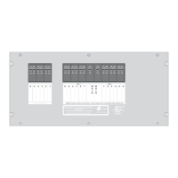
(See box drawing.)
(See box drawing, page 15.)
Connections are as follows:
()
()
Connections are as follows:
Branch circuit wires should be routed through the remaining knock-out holes in the back of the box. The wires should be
stripped and the ground wire of each cable connected to the GROUND bar terminal strip. The white or neutral wires
should all be connected to the NEUTRAL bar terminal strip. The black, or "hot" leads of all the uncontrolled loads should be
connected to their associated breakers.
If removed during installation, the white jumper wire should be re-installed between the NEUTRAL block and J6, terminal 5
of the module labeled "NEUTRAL".
The black wires to the controlled loads should be connected to the proper relay output screw terminals of J6 and J7 on the
EMS control module. Be sure these wires are under the screw terminals and that they are tight.
1 From Circuit Breaker for Relay 2
2 Output of Relay 2
3 From Circuit Breaker for Relay 1
4 Output of Relay 1
5 Neutral
1 Output of Relay 3
2 From Circuit Breaker for Relay 3
3 Output of Relay 4
4 From Circuit Breaker for Relay 4
The 12 VDC voltage connections are made through J2 (3-pin Mate-N-Lok connector on the low voltage side of the Control
Module). The +12 volts should be supplied from a source fused at 3 Amps minimum and capable of delivering up to 1 Amp
of AVERAGE current. Protecting this connection with a higher rated fuse is acceptable since the EMS is internally
protected with a 3Amp fuse.
1 + 12 Volts
2 Gen Set Run Input
3 Ground
Tighten each terminal screw to 16 in.-lb. of torque.
EMS
To insure proper operation of the source sensing circuitry on the 50 AMP EMS Model 800, jumper wires
must always be connected from a Line 1 breaker to J6 terminal 3, and from a Line 2 breaker to J6 terminal 1.
These connections must be made even though Relay 1 or Relay 2 may not be used for controlled loads.
J6 and J7 terminal blocks
NOTE
NOTE
MUST
MUST
TM
will accept up to 12 GA or 14 GA copper wire ONLY.
J6 Terminal Function
J7 Terminal Function
J2 Pin Function
be connected to a LINE 2 Breaker
be connected to a LINE 1 Breaker
8
131 Eisenhower Lane North
Lombard, IL 60148
630.268.0010 / 1.800.251.2408
50 AMP Smart Energy Management System Model 800
TM
P/N 53-00894-100 Rev. E 030807
www.intellitec.com
Intellitec
 Loading...