Do you have a question about the Intellitec 800 and is the answer not in the manual?
Details the components and functions of the EMS Display Panel.
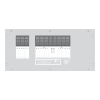
Provides information on the 50 AMP EMS Model 800 Distribution Panel.
Highlights critical safety warnings regarding electrical shock and injury.
Explains the role and types of circuit breakers used in the system.
Describes the RV Multiplex/PMC system and communication status LEDs.
Details how the EMS manages power sources and controls loads.
Explains how the EMS operates based on vehicle power sources.
Details system behavior during 240 VAC 50 Amp service input.
Describes system operation when connected to a 120 VAC generator.
Explains system behavior and load shedding for 120 VAC shore power.
Explains the function of service type LEDs and the load meter display.
Describes how to access and view stored current values for loads.
Provides guidance on installing the EMS Control Module.
Details low voltage connections for the EMS Control Module.
Explains how to configure the shedding order using dip-switches.
Specifies the dimensions for cutting a mounting hole for the panel.
Lists suitable circuit breaker brands and types for the panel.
Details the connections for the J6 terminal block on the EMS module.
Details the connections for the J7 terminal block on the EMS module.
Describes the pin configuration for the J2 power connector.
Details the wiring for low voltage load control using J4 connector.
Explains methods for controlling air conditioners via relays 5 and 6.
Provides dimensions for cutting a hole for the remote display panel.
Explains how wiring determines system configuration (Stand-Alone, Multiplex, PMC).
Outlines the steps for performing a Hi-Pot test for installation assurance.
Details the steps for testing the EMS system functionality.
Specifies the F1 fuse rating and warns against using higher ratings.
Lists pin functions for J1, J2, J3, and J4 connectors.
Details the pin functions for the J5 Display Panel connector.
Lists the functions for each position on the J6 terminal block.
Lists the functions for each position on the J7 terminal block.
Troubleshooting steps for when no 120V appliances are operational.
Steps to diagnose issues when controlled appliances fail to operate.
Guidance for when some controlled appliances work, but others do not.
Troubleshooting steps for breakers tripping upon power application.
Steps to resolve problems with air conditioner functionality.
Steps to correct issues with the determined load shedding sequence.
Troubleshooting steps for display issues like strange characters.
Steps to resolve issues with the GEN SET service indicator.
Steps to resolve issues with the 50 AMP service indicator not displaying.
| Brand | Intellitec |
|---|---|
| Model | 800 |
| Category | Measuring Instruments |
| Language | English |