TROUBLE SHOOTING (continued)
VI. Shedding order incorrect.
VII. Remote Display out, or strange characters are displayed.
VIII. Remote Display does not indicate "GEN SET" service source when generator is running.
VIX. Remote Display does not indicate "50 AMP" service source when 50 Amp 240 VAC shore power is connected.
A. Check jumper setting
B. Check relay wiring per Table on page 6.
Check wiring between J5 on EMS Control Module and Display Panel.
1 Power 12 VDC
2 Data IN ~9 VDC
3 Ground GROUND
4 RV Master OUT ~9 VDC
Both the EMS Control Module and Display Panel have internal protection.
Shorts, or mis-wiring, should not cause the units to fail.
Check wiring between generator run light circuit and J2, pin 2, on the EMS Control Module. J2, pin 2, should measure
12 VDC, or greater when generator is running and 0 VDC, otherwise.
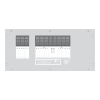
Check to make sure that jumpers are present between any LINE 1 breaker and J6, terminal 3, and any LINE 2 breaker
and J6, terminal 1. Also, check that the "NEUTRAL" jumper is in place, between J6, terminal 5 and a position on
the NEUTRAL block.
With "50 Amp" service available, the voltage between J6-3 and J6-1 should measure 240 VAC. With any other source,
the voltage between J6-3 and J6-1 should measure 0 VAC. In addition, the voltage measured between J6-3 and J6-5
should be 120 VAC and the voltage measured between J6-1 and J6-5 should be 120 VAC.
(Figure on page 5 and Tables on page 6.)
Pin Function Voltage
14
131 Eisenhower Lane North
Lombard, IL 60148
630.268.0010 / 1.800.251.2408
50 AMP Smart Energy Management System Model 800
TM
P/N 53-00894-100 Rev. E 030807
www.intellitec.com
Intellitec