87654321
CONFIGURATION DIP SWITCH (Factory Default=All On)
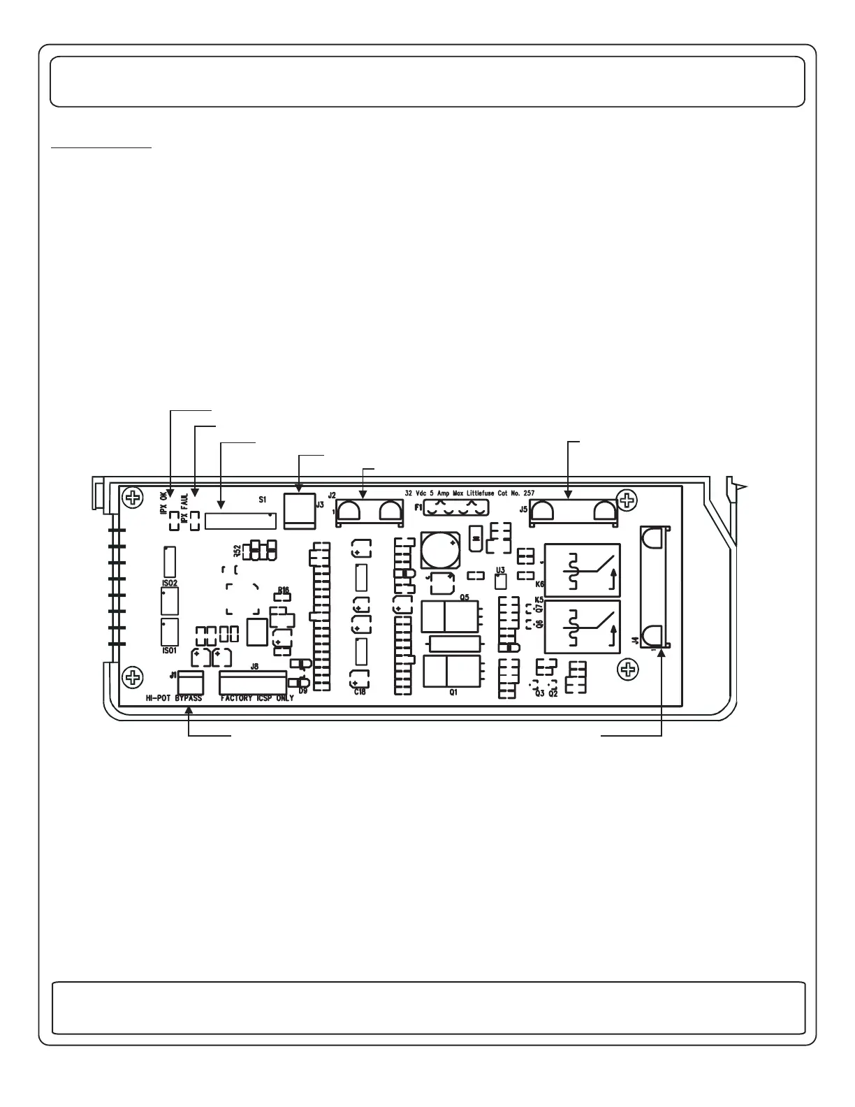
COMMUNICATIONS FAILURE IND.
COMMUNICATIONS OK IND.
HI-POT BYPASS JUMPER
POWER CONNECTOR
CURRENT TRANSDUCER INPUT
COMMUNICATION CONNECTOR
TO DISPLAY PANEL, and/or PMC,
or RV/PMC SYSTEM
LOW VOLTAGE RELAY OUTPUTS
50 AMP EMS CONTROL MODULE - LOW VOLTAGE CONNECTION SIDE
INSTALLATION
THE CONTROL MODULE
The first step when installing an EMS, is to determine which loads will be controlled and in what order they will be shed. A
typical scheme would be to control the two air conditioners, the water heater and the washer/dryer. With these loads, the first
load to be shed should be the water heater, as it's loss of operation would be the least noticed
The next would be the bedroom air, the third, the washer dryer and finally the main air. Choosing this
sequence would provide the least inconvenience to the occupants. User discretionary loads, such as microwave ovens,
coffee pots, hair dryers, etc. considered as controlled loads.
The EMS Control Module has an eight position dip-switch on the board to configure the features active in the system. The
switches in positions 1 thru 3 determine the order of shedding of the loads . The switch in position 4
determines if the Gen set EMS feature is enabled. The switch in position 5 establishes the rating of the generator. Additional
switches in positions 6 thru 8 are reserved for future control configurations.
These dip-switches are all preset to “ON” at the factory. Changing the setting of S1-1, S1-2, or S1-3 will alter the order of
shedding to suit the particular need of the installation. The following tables will assist in determining the proper settings for
S1 thru S3. Dip-switch S4 determines if energy management is enabled when 120 VAC Gen-Set service is available. If S4 is
in the “on” position, energy management will be disabled, but the Display Panel will still display total system current. If S4 is
in the “OFF” position, energy management will be enabled and the current rating of the Gen-Set needs to be selected using
dip-switch S5. With S5 set to the “ON” position, system current drawn from the generator will be limited to 45 Amps. With S5
set to the “OFF” position, system current drawn from the generator will be limited to 60 Amps.
(it would switch to operate on
gas, if needed).
should never be
(See figure below)
EMS
5
131 Eisenhower Lane North
Lombard, IL 60148
630.268.0010 / 1.800.251.2408
50 AMP Smart Energy Management System Model 800
TM
P/N 53-00894-100 Rev. E 030807
www.intellitec.com
Intellitec
 Loading...