SHEDDING ORDER DETERMINATION
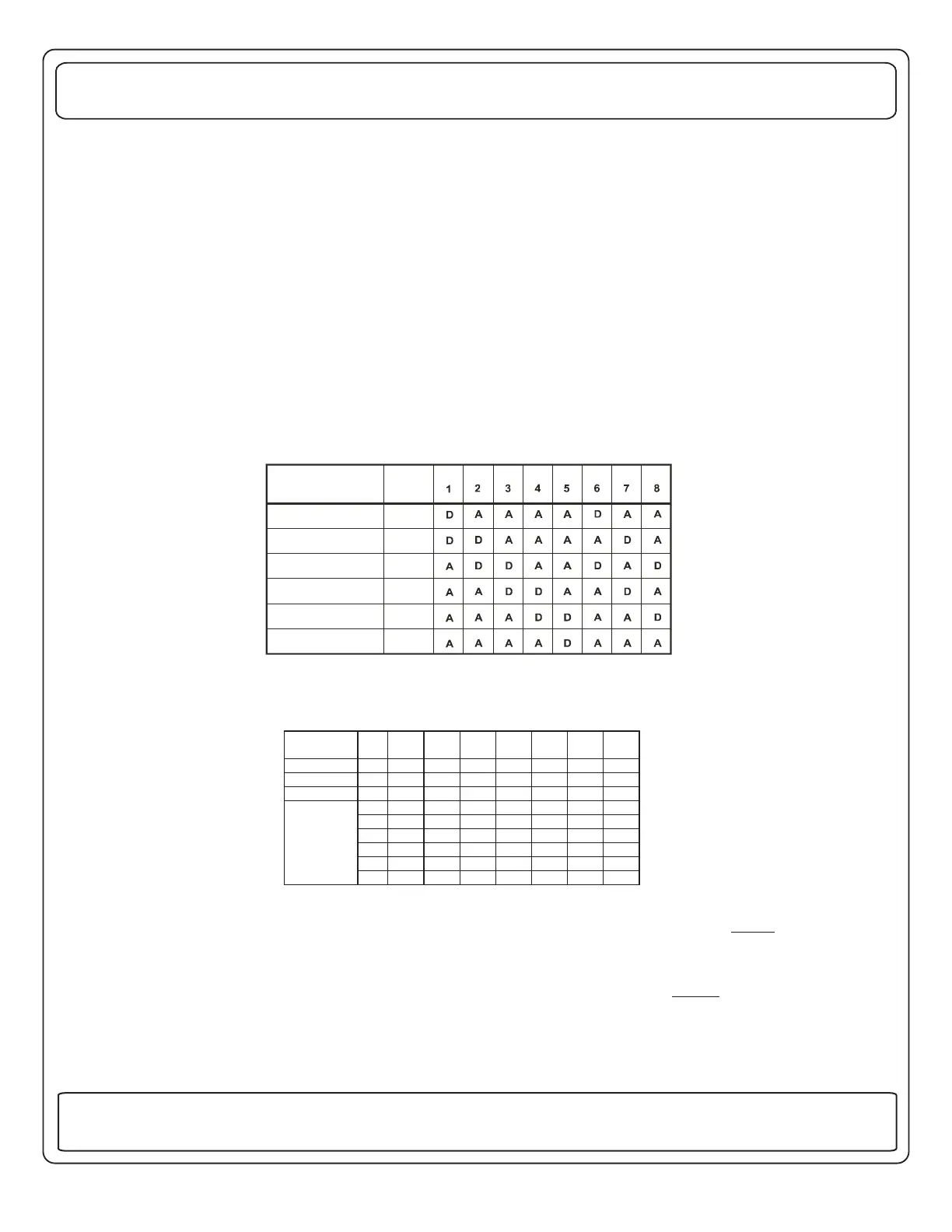
First, fill in the blanks with the names of the loads you want the system to shed, in the order they are to be shed, with the first
to be shed at the top. Then, fill in the second "Load Type" column with an "A" or a "D". "A" for a 120 VAC controlled load
such as a washer/dryer, or "D" for DC controlled load, such as a thermostat wire. You can select a maximum of 4 AC and 2
DC relays.
Starting February 23, 2007 (Julian date code 05407), position 7 has been defined for a 3rd air option feature (previously a
reserved position). When position 7 is in the off position, the 3rd air option is enabled. When position 7 is in the on position
,the 3rd air option is disabled. When the 3rd air option is enabled, the functionality of this option is as follows:
When service is 30 Amps or less, relay 1 disabled (off state) where relay 1 has been wired for a 3rd air conditioning unit.
Also, the LED on the display unit will be off for relay 1.
The 00-00903-XYZ displays have had a recent software update to allow the decoding of the relay 1 led indicator.
Displays date coded after Feb. 5, 2007 will have this software update. Intellitec Julian Date code of 030607 or newer. Julian
date code is the following: first three digits are number of days into the year and the last digits is the year.
Next, looking across the other eight columns, find the one that matches the "Load Type" column you just filled in. Using the
number at the top of the column, look in the table below to determine the settings of the three switches, S1-1, S1-2, and
S1-3. An "ON" means the switch should be closed and an "OFF" means the switch should be open.
At the bottom of each column is the Relay Shed Order. This determines which relays will be used for each load. The one at
the top of the column is first to be shed. The one below it will turn off next, and so forth. The loads be wired in this
order for the system to operate as desired.
NOTE:
MUST
Finally, the number and size of the circuit breakers should be selected to meet the needs of the installation. The breakers
can be either single, or dual types. The center two breakers on the Main Distribution Panel be 50 Amp units to act as
the Main breakers. The breakers must be obtained and then installed in the box.
MUST
(See information on breaker types later in
this manual.)
LOAD NAME
(First to Shed at Top)
LOAD
TYPE
6
COLUMN
NUMBER
12345678
S1-1 ON OFF ON OFF ON OFF ON OFF
S1-2 ON ON OFF OFF ON ON OFF OFF
S1-3 ON ON ON ON OFF OFF OFF OFF
64444644
56333463
45622536
33561352
22256225
RELAY
SHED
ORDER
(Top is
First Shed)
11115111
131 Eisenhower Lane North
Lombard, IL 60148
630.268.0010 / 1.800.251.2408
50 AMP Smart Energy Management System Model 800
TM
P/N 53-00894-100 Rev. E 030807
www.intellitec.com
Intellitec
 Loading...