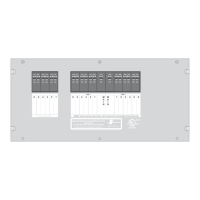
EMS CONTROL MODULE PLUGS, PINS, AND FUNCTIONS (continued)
J5 = 4 pin Molex KK .156 - Display Panel Connector Mating Housing Molex 09-50-3041
6 = 5 Position Terminal Block
J7 = 4 Position Terminal Block
J6 and J7 terminal blocks -
Pin Function
Term Function
Must be connected to a LINE 2 Breaker
Must be connected to a LINE 1 Breaker
Term Function
1 Power
2 Data IN
3 GROUND
4 RV Master Com OUT
1 From Circuit Breaker for Relay 2 ( )
2 Output of Relay 2
3 From Circuit Breaker for Relay 1 ( )
4 Output of Relay 1
5 NEUTRAL
1 Output of Relay 3
2 From Circuit Breaker for Relay 3
3 Output of Relay 4
4 From Circuit Breaker for Relay 4
J
NOTE Will accept up to 12 GA or 14 GA copper wire ONLY.
12
131 Eisenhower Lane North
Lombard, IL 60148
630.268.0010 / 1.800.251.2408
50 AMP Smart Energy Management System Model 800
TM
P/N 53-00894-100 Rev. E 030807
www.intellitec.com
Intellitec